
Lesson 8 - Heat Exchangers
This lesson focuses on the two main heat exchangers found in breweries, namely plate heat exchangers and shell and tube heat exchangers. The lesson will examine the components, assembly, and operation of these exchangers. It will also discuss how to select and size a heat exchanger and the considerations for cleaning, maintaining, and operating heat exchangers in the brewing process.
Worked Example
Let’s expand further on the example given in the previous section of chilling beer prior to filtration and show how the size of the exchanger can be calculated.
A brewery is increasing capacity and installing an additional beer filtration stream. They are requesting a new heat exchanger to chill beer before filtration for this new stream. The existing heat exchangers are plate and frame.
-
Filtration flowrate is 500 hL hr -1.
-
Beer enters the exchanger at 4°C and must be controlled to -1°C on exit. The beer stream cannot drop below the target temperature due to the risk of freezing.
-
Chilling is provided by a glycol stream supplied at -6°C and exiting at -2°C.
-
The overall heat transfer coefficient for the exchanger is 2,500 Wm-2 K-1.
-
The specific heat of beer is 4,100 J kg-1 °C-1 and for glycol is 3,400 J kg-1 °C-1.
-
The density of beer is 1,004 kg m-3 and for glycol is 1,035 kg m-3.
What is the required surface area for the new heat exchanger?
If the dimensions of the exchanger plates were 0.4 m wide by 0.8 m high, how many plates would be required?
What is the glycol volumetric flowrate (m3 hr-1) required to achieve the beer outlet temperature?
Let’s work through the scenario step by step.
1. The first step in heat exchanger sizing is to select the type of exchanger and decide on the flow configuration.
As the existing exchangers are plate heat exchangers, it seems sensible to select the same type for the new exchanger. A co-current flow configuration is selected because of the temperature sensitivity of the beer stream.
2. The second step is to draw the temperature profile.
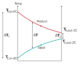
3. Once you have a clear picture of the temperature profile, it is then possible to calculate ∆LM.
First, start by calculating the temperature differences at the inlet ∆T1 and outlet ∆T2 of the exchanger.

And

Now you can use the values calculated for ∆T1 and ∆T2 to determine ∆TLM


4. Next, convert the beer volumetric flowrate in hL hr-1 to mass flowrate in kg s-1.


5. Next, use the formula for fluid that is being cooled down – calculate the heat transfer rate of the product stream.


You can see that the heat transfer rate of the beer is negative as the beer is losing heat (cooling down) as opposed to gaining heat. However, when q is used to calculate heat exchanger area it makes no difference if the heat is gained or loss and so the negative sign is dropped. Plus, you can't buy a negative number of heat exchanger plates!
6. After this, use the formulae for overall heat transfer rate across an exchanger – calculate the heat transfer surface area.


7. Calculate the surface area of one plate.


8. Calculate the number of plates.


This can be rounded up to 92 plates. If each plate is 2 mm thick, the plates have a 3 mm spacing, and the end plates were 10 cm thick each, the length of the exchanger would be:


So, the dimension of the heat exchanger will be 0.8 m high × 0.4 m wide × 0.7 m long.
If on the first calculation, any of these dimensions seem unrealistic, new values can be used for the dimensions of the exchanger plates. The calculation can be redone until the exchanger is of a reasonable dimension.
From this, a supplier would do further detail design of the exchanger, optimising for surface area, pressure drop and cost.
9. We can calculate glycol mass flowrate by using the equation for heat transfer rate in a fluid that is being heated up.


The value for q used is the same as calculated in question 4 above except now we use it positive as the glycol is gaining heat (because it is warming up) rather than losing it.
10. Finally, we can calculate the glycol volumetric flowrate


The volumetric flow of glycol through the exchanger is 73 m3 hr-1. This is almost 50% greater than the beer flowrate of 50 m3 hr-1. This could present a concern in the exchanger design as a large difference in the flowrates on either side of the plates will create a large pressure difference across the plates. This can cause the plates to bend and ultimately lead to leakage through the gasket.
A heat exchanger can be designed and sized to the exact performance specifications, but ultimately its performance is determined by how well it is operated and maintained. In the next sections, we will look at some practical considerations for cleaning, maintaining, and operating heat exchangers in the brewing process.