
Lesson 8 - Heat Exchangers
This lesson focuses on the two main heat exchangers found in breweries, namely plate heat exchangers and shell and tube heat exchangers. The lesson will examine the components, assembly, and operation of these exchangers. It will also discuss how to select and size a heat exchanger and the considerations for cleaning, maintaining, and operating heat exchangers in the brewing process.
Point of Reflection – Reconvene
Welcome back. So, what were your thoughts?
Did you observe that the two fluids are flowing in opposite directions in the heat exchanger so the flow configuration is countercurrent? Each fluid only passed through the exchanger once making it a single-pass exchanger.
Earlier in this lesson, we explained why an exchanger might be designed in a co-current rather than a countercurrent flow configuration. This is easily achieved in a plate heat exchanger by changing the position of the inlet and outlet ports of one of the fluids, e.g. in the figure below.
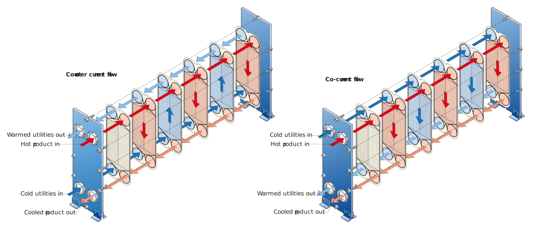
Figure: Exchanger configuration for countercurrent (left) and co-current (right)
Multiple passes
Earlier in this lesson, we also explained the applications and benefits of multi-pass heat exchangers. Multiple passes in a plate heat exchanger are achieved by inserting plates with blanked ports inside the exchanger. If only one of the fluids is required to be multi-pass, then only the distribution ports of that fluid are blanked. If both fluids are required to pass multiple times through the exchanger, then both distribution ports will be blanked.
A typical wort cooler plate heat exchanger can have up to eight passes.
In multi-pass plate heat exchangers, there are ports on both the fixed and moveable end covers. Before the exchanger can be opened, the piping at the moveable end has to be disconnected and removed.
The video clip below shows how a multi-pass plate heat exchanger can be configured using a plate with two blanked ports positioned inside the exchanger. You will also see in the video the inlet and outlet ports on both sides of the exchanger. Note, this is for illustrative purposes only and is not a recommendation or endorsement of the supplier’s product.
Split flow
You have already learned that pressure drop across a plate heat exchanger can be a limiting factor in heat exchanger design. One way this can be overcome is by splitting the flow through the exchanger. These configurations are shown in the figure below:
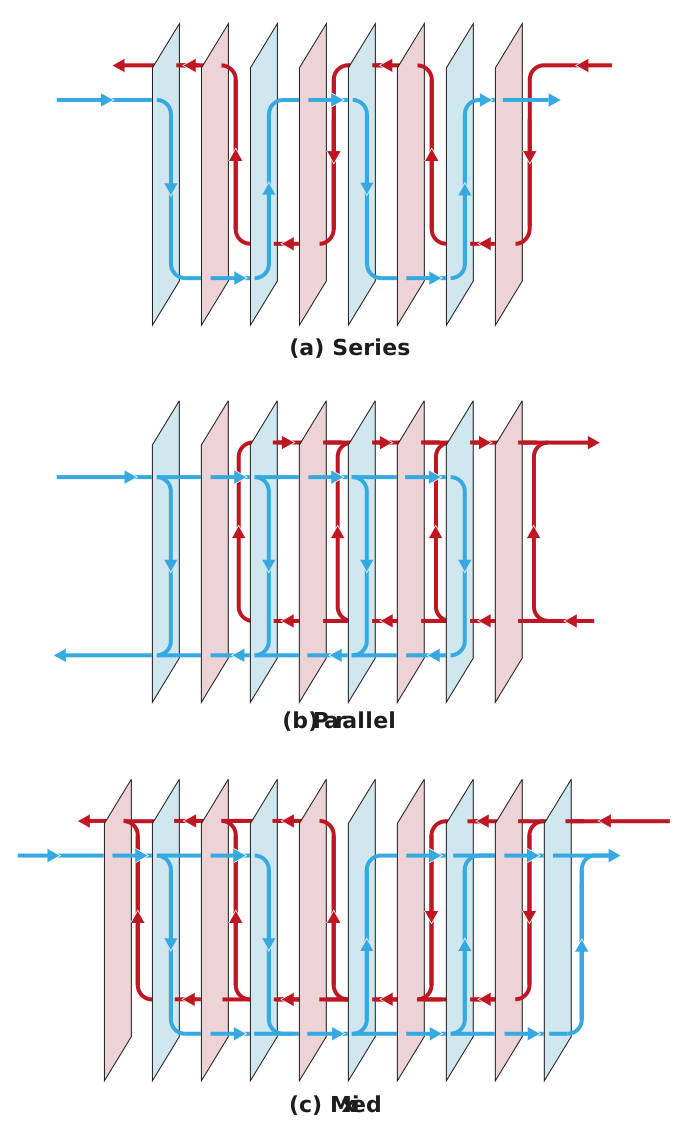
Figure: Series (a), parallel (b) and mixed (c) flow configurations in a plate heat exchanger
The configurations in the above figure can be explained as follows:
-
In figure (a) each fluid is a single stream passing multiple times through the exchanger. The flow path of the stream is long, so the pressure drop is high.
-
In figure (b) each fluid is split into multiple streams flowing in parallel through the exchanger. This shortens the flow path, which lowers the pressure drop across the exchanger.
-
The disadvantage of a shorter flow path, like in figure (b), is that the potential heat transfer amount can be restricted. Figure (c) offers a combined solution that can still offer good heat transfer and reduced pressure drops.
You now have a practical understanding of plate heat exchangers used in the brewing process. Let’s continue our exchange as we head into the next few sections where we learn more about another type of heat exchanger, the shell and tube heat exchanger.