
Lesson 8 - Heat Exchangers
This lesson focuses on the two main heat exchangers found in breweries, namely plate heat exchangers and shell and tube heat exchangers. The lesson will examine the components, assembly, and operation of these exchangers. It will also discuss how to select and size a heat exchanger and the considerations for cleaning, maintaining, and operating heat exchangers in the brewing process.
Temperature Driving Force in Heat Exchangers
Earlier in this lesson, we introduced temperature driving force (∆T) and how it impacts on heat exchanger design. Now that you better understand heat transfer in a heat exchanger, we will look more closely at the temperature driving force in heat exchangers.
In the figure below we can see that the temperature difference between the hot and cold stream varies depending on their position through the exchanger for a co-current (left) and countercurrent (right) exchanger.
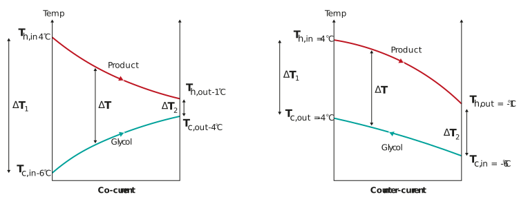
Figure: The temperature difference profile for co-current and counter current flow exchangers
As we have shown previously, the heat transfer rate across a heat exchanger is driven by the temperature difference between the streams, but in the figure above, which temperature difference should be used?
-
The temperature difference between the inlet streams ∆T1
or
-
The temperature difference between the outlet streams ∆T2
Neither of these would be a precise representation of the complete exchanger profile, and the calculated heat transfer rate would be incorrect.
It has been shown that the most accurate way to determine the temperature driving force through a heat exchanger is the log mean temperature difference (∆TLM).
∆TLM is defined as the average temperature difference between two fluid streams across the heat exchanger. The greater the ∆TLM, the greater the heat transfer rate.
The ∆TLM of an exchanger is calculated as follows:

Referring to the image above:
For co-current flow

And for countercurrent flow

When calculating ∆TLM it useful to draw a temperature profile diagram, like the one shown in the figure above. On the profile, mark Tc,in, Th,in, Tc,out and Th,out. Then calculate ∆T1 and ∆T2 on each side of the diagram. This will help you identify the correct inputs into the calculation for ∆TLM
In multi-pass heat exchangers, the log mean temperature difference may be calculated as follows:

Where f is an empirically derived correction factor based on the number of passes and ratios of the inlet and outlet temperatures.
You will recall that approach temperature is when the temperature of one fluid approaches that of the other, thus reducing the temperature driving force. As we can see in the figures above, this occurs at the end of the heat exchanger where the product stream leaves.
Heat exchangers with good overall heat transfer coefficients can handle small approach temperatures with less impact on the surface area. For example, the approach temperature in a plate heat exchanger may be as low as 1°C without requiring many plates. In contrast, in shell and tube heat exchangers an approach temperature of 5°C or more is recommended for realistic surface areas.
We have covered the elements that define the overall heat transfer rate for a heat exchanger with multiple heat transfer mechanisms. In the next section, we will learn how this, and other heat transfer rate definitions can be used to size a heat exchanger.