
Lesson 8 - Heat Exchangers
This lesson focuses on the two main heat exchangers found in breweries, namely plate heat exchangers and shell and tube heat exchangers. The lesson will examine the components, assembly, and operation of these exchangers. It will also discuss how to select and size a heat exchanger and the considerations for cleaning, maintaining, and operating heat exchangers in the brewing process.
Flow Configurations in Heat Exchangers
Exchangers are designed so the fluids flow in a specific direction relative to each other. In this section, we will review the common flow configurations and how they impact on heat transfer.
A heat exchanger’s flow configuration influences the temperature change of each fluid across the exchanger, which in turn impacts on the amount of heat transfer that occurs in the exchanger. It also influences the heat transfer surface temperature, which we will explain further in this section.
There are four common flow arrangements, as illustrated in the diagrams below:
-
Countercurrent – the two fluids flow parallel to each other in opposite directions. This is the most common flow configuration in heat exchangers. It allows for the largest change in temperature of both fluids and therefore the greatest amount of heat transfer between fluids.
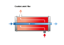
Figure: Countercurrent flow in a heat exchanger
-
Co-current flow – the two fluids also flow parallel to each other but in the same direction. This configuration is less efficient than countercurrent flow but does provide more uniform wall temperatures. This configuration is used when the product fluid is sensitive to the operating temperature of the exchanger.
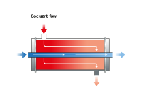
Figure: Cocurrent flow in a heat exchanger
-
Crossflow – the two fluids flow in a direction that is 90° to each other. The efficiencies of heat exchangers with this flow configuration fall between that of countercurrent and co-current heat exchangers.
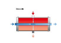
Figure: Crossflow in a heat exchanger
-
Hybrid flow – this is when there is a combination of co-current, countercurrent, and/or cross-current flow. These types of heat exchangers are typically used to accommodate the limitations of an application, such as space, budget costs, or temperature and pressure requirements.
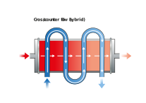
Figure: Hybrid flow in a heat exchanger
The configurations described above represent idealisations of what truly occurs; it is never possible, in practice, to make the flow patterns conform to the ideal.
Using the example of product being cooled from 5°C to 2°C by glycol supplied at -5°C and returned at -3°C, let’s review the relative merits of two of the flow configurations found in heat exchangers, countercurrent and co-current.
Countercurrent flow
The figure below shows how in countercurrent flow, where the product is required to be at its coldest is also where the glycol is at its coldest, and where product is at its warmest so too is the glycol. This allows for the greatest temperature differences within the exchanger fluids which allows countercurrent flow heat exchangers to achieve far greater heat recoveries compared to co-current exchangers.
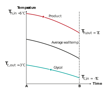
Figure: The temperature profile for countercurrent flow configuration
The figure above illustrates the only real limitation of countercurrent flow configuration. In the figure the exchanger wall temperature changes significantly across the exchanger and drops to as low as -1.8°C. Depending on the product, this temperature could be lower than the fluid’s freezing point and hence there is a significant risk of freezing in the exchanger.
Because of its superior heat recoveries, countercurrent flow will always be the preferred configuration unless the product fluid is highly sensitive to the operating temperatures inside the heat exchanger.
Co-current flow
As we can see in the figure below in co-current flow, the exchanger wall temperature is far more uniform and in this example does not drop below 0.5°C. This is warmer than the equivalent example with countercurrent flow, and shows why this configuration is preferred for temperature sensitive products.
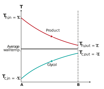
Figure: The temperature profile for co-current flow configuration
The above figure however, also shows the limitations of co-current flow. Where the product is required to be at its coldest the glycol is in fact at its warmest. This limits the temperature change of the product and glycol streams and so too the heat transfer across the exchanger.
To ensure that a co-current exchanger can still achieve the specified heat transfer despite these limitations, the design is adjusted as follows:
-
The product fluid temperature change is kept small
-
The flowrate of the utility fluid is increased
-
The surface area of the exchanger is increased.
Now that we understand the different flow configurations of heat exchangers and their benefits let’s look at another element of exchanger flow, which is the number of passes.