
Lesson 10 - Carbon Dioxide Recovery Technology
This lesson explores the technology used to recover and purify carbon dioxide (CO2), which is a co-product from brewery fermentations. Purified CO2 is used throughout the brewery to carbonate liquids and to purge air (oxygen) from vessels and packaging containers. It examines the role that fermentation and fermenter vessel operation has on the availability of CO2 for collection, as well as considering an overview of the technologies and plant involved in collecting, purifying, and liquefying CO2 for use back in the brewery.
Condensing
The gas is now cooled to around -20 °C and condensed or liquefied. Any incondensable gases, such as oxygen and nitrogen, are vented out of the condenser resulting in the liquefied CO2 increasing in purity. This is a form of purification and liquefaction.
We wish to condense (i.e. the production of a liquid from a gas or vapour) the gaseous CO2 for the following reasons:
1. To significantly increase the density of the CO2 to efficiently store a large amount in one (storage tank) volume.
Condensation satisfies requirement one as liquids have much higher densities than gases. We can store a greater mass of liquid in a given volume compared to a gas.
2. To remove any non-condensable gases, e.g. oxygen and nitrogen are not condensable at the pressures and temperatures used during CO2 condensation, but they are soluble in liquid CO2 if left in contact with it (see below).
Through the orientation of the condenser (more below), and the differing densities of condensed CO2 liquid and non-condensable gases, we can separate the gases by allowing them to rise to the top of the condenser and vent them from there.
Condensable versus soluble – it is important to understand the difference. Think of a volume of pure liquid water at room temperature in contact with atmospheric air. We know that the air, and its components of oxygen and nitrogen, etc., are soluble in the water, i.e. the gases are capable of being dissolved in another liquid. But we intuitively know that we cannot condense atmospheric air at room temperature, i.e. we cannot turn the gaseous air into liquid air. So, in this case, we can dissolve air into water, but we cannot condense the air (or any of its components) at the pressure and temperature described.
The condenser is typically a shell-and-tube heat exchanger (discussed in the Heat Transfer Unit). As a quick reminder, it is a large cylindrical vessel (the shell), with a separate set of tubes routed through it. A separate inlet and outlet are provided through the shell as well as through the tubes. This is so the CO2 gas can enter and be condensed against the outside of the tubes, which contain a refrigerant (typically ammonia). The separate flow paths allow the CO2 and refrigerant to be kept separate.
Any incondensable gases present will not condense against the cold tubes and will rise to the top of the shell and accumulate there. As more CO2 is condensed, greater quantities of incondensable gases accumulate and eventually start to blanket the tubes and slow down the rate at which CO2 will condense. This is not desirable! However, we can easily use a vent valve installed at the top of the shell to vent these incondensable gases to the atmosphere. This set-up is shown schematically below.
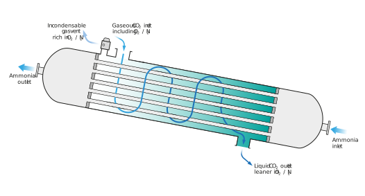
Figure: A shell-and-tube CO2 condenser showing the gaseous CO2 (on the shell side), ammonia refrigerant (tube side), and the incondensable vent