
Lesson 8 - Refrigeration Technology
This lesson takes a closer look at refrigeration technology. It reviews the different primary and secondary refrigerants and explores the technology required to deliver primary refrigeration to the brewery. It concludes by looking at how refrigeration is used within the brewery.
Point of Reflection – Reconvene
Welcome back. So, what were your thoughts?
First, let’s look at a typical Mollier diagram for a refrigerant. We’ll use R134a (tetrafluoroethane, CF3CH 2F) in this example.
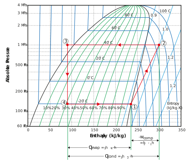
Figure: Mollier diagram
Evaporation occurs in the area between points 4 to 1. As you should recall, this represents the cooling energy obtained from the process. Ideally, this should be possible at a temperature just below the minimum process temperature required. The latent heat of vaporisation should be as high as possible in order to minimise the volume of refrigerant required in the process.
The pressure at this point (line 4-1) should be above atmospheric pressure so that vacuum conditions are avoided.
The refrigerant is condensed between points 2 to 3. This is limited by the performance of the condensers, which is reliant on the ambient conditions. The higher the ambient temperature, the higher the pressure that will be required. In terms of the refrigerant, this pressure should be as low as possible to both minimise the compression energy and to also ensure that the costs of manufacturing the equipment for higher pressures is no too expensive.
Compression occurs between points 1 and 2. The amount of compression required is driven by the operating temperatures and the characteristics of the refrigerant when it comes to compression.
The refrigerant used should have the best possible coefficient of performance (COP), subject to the other constraints such as maximum pressures within the application’s specific conditions.
Although we used R134a as an example, the properties shown here can be evaluated against any refrigerant.
Physical properties of refrigerants
Now that you have worked out which properties are ideal, it is important to understand that different refrigerants will perform better under different conditions. The figure below shows the temperature-pressure lines for various refrigerants.
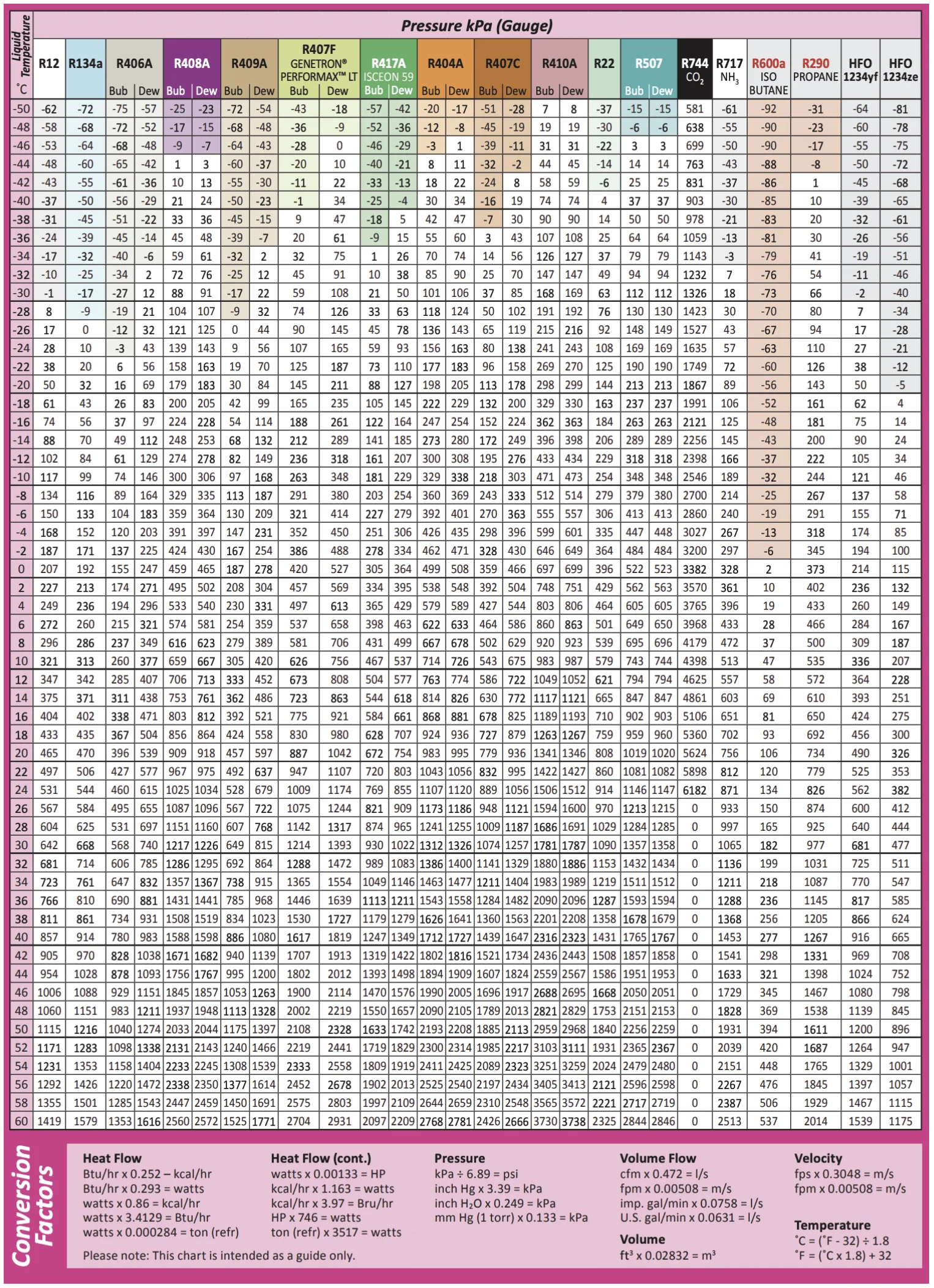
Figure: Temperature-pressure lines for various refrigerants (supplied by A-GAS)
Although negative pressure was not plotted this is possible for the refrigerant to achieve. However, we prefer not to have this in a refrigeration circuit because if there are any leaks, a vacuum has the potential to suck in air from the atmosphere.
After taking a quick look at this figure, you can see why ammonia is so widely used.
Let’s have a look at some of the common primary refrigerants used in breweries.