
Lesson 2 - Wort Separation Principles
This lesson deals with the principles of wort separation. Before wort separation, we have completed mash conversion. We will now need to separate the liquid wort from insoluble material. This is mainly the husks from the malt, known as spent grain. We will review the reasons why filtered wort must be clear, and how this affects wort quality. We will examine how the all-important grain filter bed is formed differently, by each of the three most common mash separation devices. These devices are: the lauter tun, the mash filter and the mash tun. We will investigate a typical wort collection profile, which ends with the removal of the spent grain.
Darcy’s Law describes filtration flow rate. We will assess both the variables involved, and what influences them. We will finally use Darcy’s Law to predict the relative flow rates of the three mash separation devices.
The Effect of Differential Pressure (DP) on Filter Flow Rate
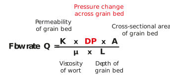
Figure: The Darcy equation and differential pressure (DP)
DP is a top line variable in the Darcy equation and a higher value should result in a higher flow rate and vice versa.
Darcy’s Law predicts that a higher differential pressure across the grain bed will give us a higher flow rate. This was true for Darcy’s filter, which was a bed of sand. A sand bed is non-compressible; its bed permeability does not change during use. However, our grain bed is compressible. As we increase flow rate, the grain bed will compress and its permeability will decrease significantly. To avoid this, mash separation devices operate with a low differential pressure across the grain bed; it effectively cannot be used to increase filter flow rate.
If we connect some clear piping to the underside of the false floor of a lauter tun, we can use this as a U tube manometer to indicate pressure change beneath the false floor. While in a stationary no-flow situation, the wort level in the tubing will rise to be at the same level as the supernatant wort.
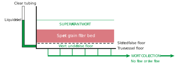
Figure: Using a manometer for DP monitoring – low/slow flow
If we now start a low flow rate from under the floor, the grain bed will allow free flow through it according to the wort viscosity, the grain bed permeability, and the grain bed loading. There is little difference between the pressure under the false floor, and the pressure above the grain bed. The manometer level changes little.
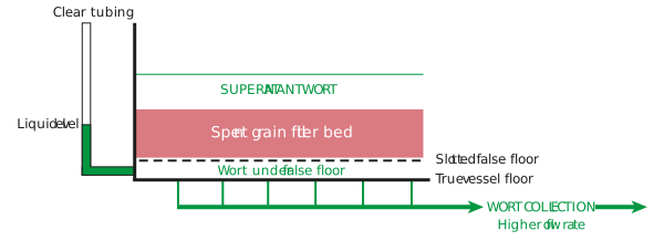
Figure: Using a manometer for DP monitoring – high flow rate
As we further increase the wort collection flow rate, the grain bed will start to compress and its permeability will decrease. The ‘capability’ of flow through the grain bed then reduces. Once the wort collection flow rate exceeds the bed ‘capability’ flow rate, we will see the pressure under the false floor drop. This will result in a level drop in our manometer tube. This tells us that we are trying to collect wort faster than the bed can release it.
This difference between the pressure below the false floor and above the bed is what we call the ‘differential pressure’. The wort separation device will have a limitation on the amount of DP it can withstand. If we exceed it, the false floor could collapse! If we reach the differential pressure limit of the device during wort collection, we need to reduce the wort collection flow rate.
The manometer is a simple way for us to monitor DP. It can be used with manually operated devices. If wort collection is being done automatically, then DP will be measured by comparing readings from pressure transmitters located both above and below the false floor.
Let us now finally take a look at how all of the Darcy’s Law variables combine together to predict the relative wort filtration flow rate of our mash separation devices.