
Lesson 8 - Gases
In this lesson we take a closer look at gases, including compressed air. We will look at the quality requirements and specifications for use in the brewery. Different compressed air generation methods will be considered. For nitrogen and oxygen, we will look at the common uses, quality requirements, and options available for supply, storage, usage, and generation.
Liquid Nitrogen and Oxygen
Liquid nitrogen and oxygen are delivered and stored cryogenically (meaning at extremely low temperatures), and the delivery systems are identical other than a few minor differences in storage temperature and pressure.
The reason these are often supplied as liquids is that they take up less space in liquid form than they do as gases. Liquid nitrogen and oxygen are made by means of a liquefaction process. We won’t delve into this, as it doesn’t make sense to do this on site. Liquid can be delivered either in bulk or in smaller portable containers.
Carbon dioxide and the recovery thereof is covered in the next teaching lesson, however the storage and vaporisation of liquid carbon dioxide is essentially the same as for liquid nitrogen and liquid oxygen. In instances where it is not economical to recover carbon dioxide from the process it can be delivered to the brewery.
Bulk liquid storage
The figure below shows a typical installation of a bulk system
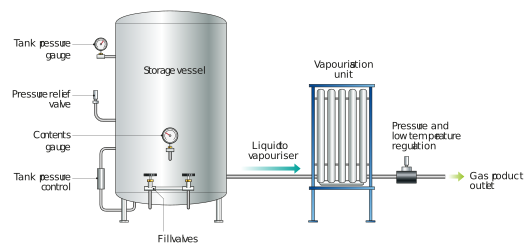
Figure: Typical cryogenic storage and supply system
The bulk system consists of a bulk storage tank, vaporiser, and distribution to the plant. Because of the extremely low temperatures of the liquids in the tank, they are normally vacuum insulated. This operates like a ‘thermos’ flask, with a vacuum between the two walls to prevent heat loss – or in this case, with an oxygen tank to reduce heat gain.
The pressure in the tank must be carefully maintained. To do this, two systems are required. Firstly, a pressure-building loop is incorporated to prevent the tank pressure dropping as liquid runs to the vaporiser. The loop vaporises the liquid to replace the lost pressure. Secondly, if the pressure is too high, gas is vented. The vented gas can be supplied directly from the tank to the brewery distribution line. The figure below shows a typical storage tank in greater detail.
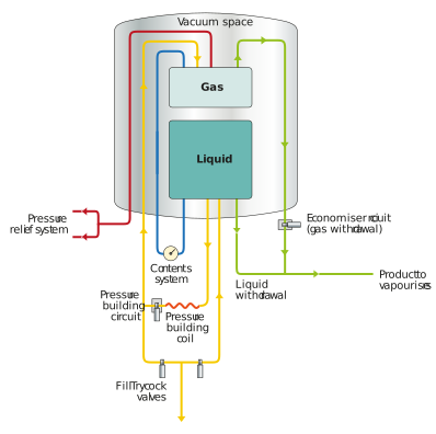
Figure: Typical cryogenic storage vessel
The pressure-building and pressure-relief systems are shown in the figure above. As we can see, gas withdrawal can be sent to the brewery. Liquid nitrogen can also be withdrawn from the tank if required in the plant.
Vaporisers
In order to convert the liquid into gas to supply to the brewery, vaporisers are used. Most vaporisers are ambient vaporisers, although we can also find forced-air, steam, or electrical vaporisers.
Vaporisers are sized based on the gas flow required. They are essentially finned heat exchangers. The liquid passes through them, and as it absorbs heat from the atmosphere the liquid vaporises and it turns into gas. Typically, the first third of the vaporiser is where the liquid-to-gas vaporisation happens. The second third of the exchanger is where the cold gas warms up. The final third is normally seen as a safety zone to ensure that the gas temperatures supplied to the plant are not too low. The figure below shows how a vaporiser fin set works.
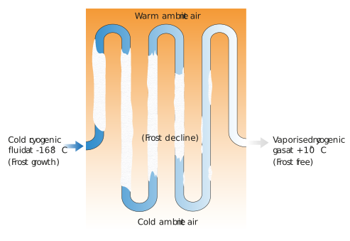
Figure: What happens in the different stages of a vaporiser
As you can see, ice builds up in the first two sections. To facilitate melting, the fins in the first section normally have more space between them. This also prevents the fins being damaged by the accumulation of the ice that is formed. The difference between the liquid section fin and the gas section fin is shown in the figure below.
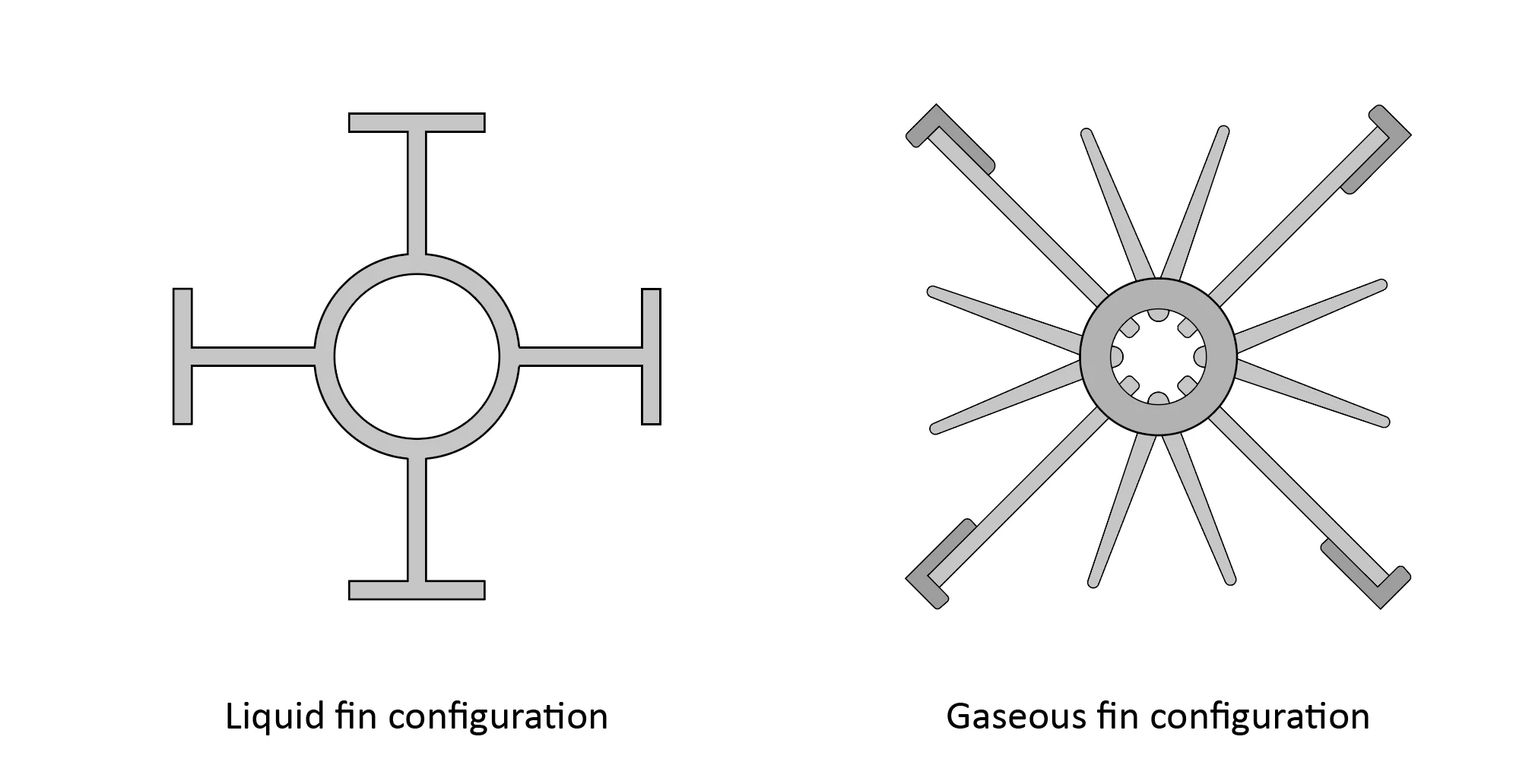
Figure: Typical liquid section and gas section fin configuration
An important aspect of the vaporiser is to protect the plant from liquid or overly cold gas entering it. Thus, liquid detecting and temperature monitoring are normally included in the safety features.
The gas to the brewery is normally controlled at a set pressure by means of pressure regulators.
Liquid nitrogen and oxygen canisters
Liquid nitrogen and oxygen can also be delivered in cryogenic canisters. These canisters can be set up to supply liquid or gas. The figure below shows the typical design for the two options.
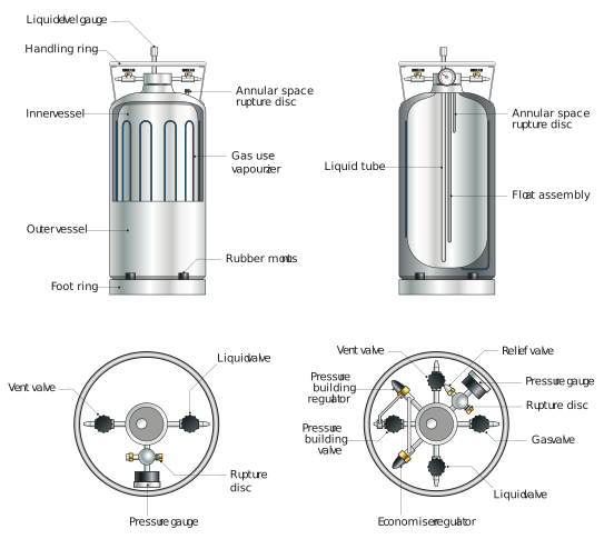
Figure: Typical cryogenic canisters for liquid oxygen and nitrogen
Where gas is required, the canisters are fitted with an internal vaporiser.