
Lesson 6 - Refrigeration Theory and Cycle
This lesson explains the concepts of refrigeration. It describes the cycle that is utilised in all refrigeration systems and identifies where such systems are found in a brewery.
Energy Quantification
An energy balance can be used within the OVC cycle to quantify the heat that is being removed, and the work that needs to be done in order for the cycle to operate.
For each step, we will have a value, Q, for the energy being supplied or removed from the system.
-
The compressor will need to have an energy supply, Qw, to perform the work to compress the gas.
-
The condenser will need to release energy (heat), Qc, to condense the refrigerant from vapour to liquid.
-
The evaporator will gain a certain amount of energy (heat), Qe, from what is being cooled. This is called the cooling load.
The expansion value is the only component of the OVC cycle that does not change the enthalpy (energy) of the system. Therefore, there is no need to have a Q for the expansion value.
The overall energy balance is quite simply energy in = energy out. In mathematical terms, this is shown as:

To write an energy balance for the OVC cycle, we can use the terms described above, and put them on the appropriate side of the energy balance. The energy going into the system is the heat gain into the evaporator, as well as the energy required for the compressor. The energy out is the heat released from the condenser. Therefore, the energy balance becomes:

This energy balance can be used to determine how much energy is being transferred in the system. We can use the Mollier diagram to determine the value of each of these terms.
The rate of heat transfer can be calculated given the difference in enthalpy from one state to another as:

Where:
Q is the energy in kJ
M is the mass of refrigerant in kg
∆H is the enthalpy change from initial to final states, Hfinal − Hinitial in kJ kg-1
In our original example, we can then define the equations for 
 and as follows:


If we enter these equations into the overall energy balance, we then have:

Since  is in every term, we can cancel it out and we are left with:

This balance can be used to determine the amount of work needed.
Q and q
These equations can be used to calculate heat as Q or q. Q is the total amount of heat in joules while q is the rate of heat transfer in watts (joules per second). The difference between these is the element of time. The two are interchangeable in the above equations by using mass (in kilograms) or mass flow rate (in kilogram per second). In other words the equation above of Q = M∆H can also be represented as q = m∆H where q is the energy transfer rate and m is the mass flowrate
The Mollier diagram is used to determine the enthalpy at the state the refrigerant is in. For example, at the exit of the condenser, the refrigerant is a subcooled liquid at a certain pressure. The diagram can be used to find the enthalpy at that state.
Finally, let’s look at an example that brings all of this together by referring to the figure below.
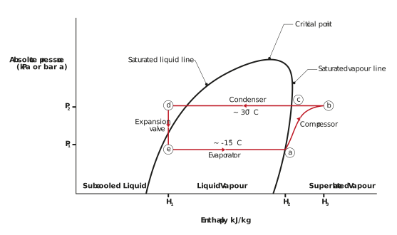
Figure: Illustration of an OVC cycle on a Mollier diagram
A cold storage room needs to be maintained at 4°C. It has been determined that the enthalpy of the refrigerant at states (d), (a), and (b) are 242, 387, and 424 kJ kg-1 respectively. The mass flow rate of refrigerant is 872 kg/hr. Determine the cooling load rate.
Recall that the cooling load Qe is:
Qe = M (H2 − H1)
But in this example we are required to calculate the cooling load rate using the mass flowrate so we use:
qe = m (H2 − H1)
Enter our values, and we get:
qe = 872 × (387 − 242) = 126,440 kJ hr-1
Remember, refrigeration is one of the most demanding functions within a brewery/packaging plant. It is therefore important to determine and monitor the efficiency of the refrigeration plant. We will discuss this in the next section.