
Lesson 6 - Refrigeration Theory and Cycle
This lesson explains the concepts of refrigeration. It describes the cycle that is utilised in all refrigeration systems and identifies where such systems are found in a brewery.
Refrigeration Cycle
The main function of a refrigeration process is to remove heat from a fluid. We know that heat always flows from high to low temperature, and this is the driving force for refrigeration processes.
Prior to introducing all the technology that goes into refrigeration systems, we must understand the overall process that occurs in order to remove heat. A refrigeration system, such as a green beer chiller, must include the following four steps that occur in a cycle: compression, condensation, expansion, and evaporation. The cycle exploits two important properties of the primary refrigerant:
-
Heat is either absorbed or released during a phase change between vapour and liquid.
-
The temperature of the phase change will depend on the pressure; so by changing the operation pressures, the temperatures of condensation and evaporation will also change.
This cycle is known as the ‘ordinary vapour compression cycle’ or more commonly the ‘OVC cycle’.
It is important to know that in every step of the OVC cycle, we are either changing pressure (and temperature), or changing phase. The equipment is being used to alter the pressure or phase of the primary refrigerant, and in doing so, is transferring heat from one area to another.
The following figure illustrates that there is primarily a high pressure (high temperature) side, and a low pressure (low temperature) side of the cycle.
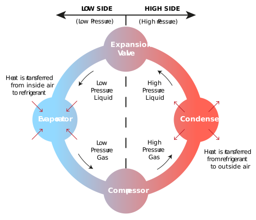
Figure: Refrigeration cycle
Let’s take a closer look at each step, and break down what is going on. For this to work, the system operates between two pressures.
-
The evaporation pressure of the primary refrigerant at evaporation temperature.
-
The condensing pressure of the primary refrigerant at condensing temperature.
The reason for this is best described using a Mollier diagram. You should recall that a Mollier diagram is a graphical representation of the relationship between pressure and enthalpy of a given substance. For example, to confirm the correct operating pressures for a refrigeration system using ammonia as the primary refrigerant, we can consult a Mollier diagram for ammonia to check the status of the system. An example of this is given below.
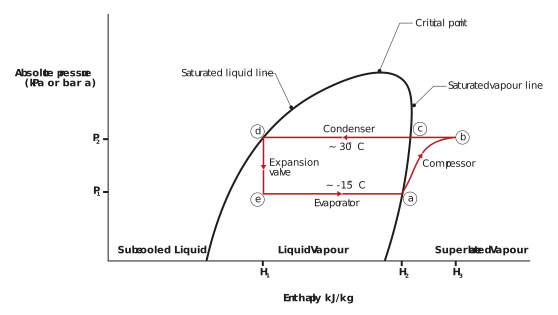
Figure: Illustration of an OVC cycle on a Mollier diagram
On the x-axis of the Mollier diagram, we have enthalpy in kJ kg-1, and on the y-axis we have absolute pressure in kPa a or bar a.
Remember, at a specific set of conditions, all matter has a specific enthalpy that is equivalent to the total heat content.
The Mollier diagram enables us to see the corresponding enthalpy changes that occur by changing the pressure or phase of a substance. Moreover, it allows us to see how heat is transferred in the OVC cycle. Let’s break down the OVC cycle using the Mollier diagram above.
-
Starting at point (a) on the figure, the primary refrigerant is a saturated vapour, which has enthalpy, H2 Remember, a saturated vapour holds all the enthalpy possible at that temperature and pressure.
-
Increasing the pressure (compressing) from P1 to P2, brings us to point (b). The increase in pressure pushes the vapour into a superheated vapour phase, which contains more heat and more enthalpy, H3.
-
Next, the refrigerant flows to the condenser, where heat (enthalpy) is removed. This happens at constant pressure, P2. Condensing the superheated vapour moves us back to a saturated vapour phase at point (c).
-
Complete condensation of the saturated vapour releases enthalpy, which brings us to a saturated liquid, point (d). The removal of heat (enthalpy) has placed us back at a much lower enthalpy, H1, while remaining at constant temperature. If enough heat is removed, it will become a subcooled liquid outside of the saturated liquid line. A subcooled liquid is a liquid that has been cooled to a temperature below its saturation temperature, at a given pressure. If the condenser can remove enough heat to move into the subcooled region, the system will likely be more efficient.
-
Next, an expansion valve releases the pressure down from P2 to P1 which brings us to point (e). Decreasing the pressure consequently decreases the temperature, and a mixture of liquid and gas is created. The enthalpy remains at H1. The refrigerant at this point is a mixture of liquid and vapour, which will then flow into the evaporator. This expansion is said to be isenthalpic, which means that it occurs at constant enthalpy.
-
Now we are at point (e) on the figure. The evaporator pulls heat from the heat source to evaporate the refrigerant. This causes an increase in enthalpy, back to H2. The transition from point (e) to point (a) represents the refrigeration effect.
To recap, the four steps in the OVC cycle are:
-
The evaporator draws heat in, and uses the heat to evaporate the primary refrigerant into a vapour at the evaporation pressure. This causes an increase in enthalpy.
-
The compressor compresses the vapour to a higher pressure, causing the refrigerant to become superheated. This increases the enthalpy even more.
-
The condenser then removes the enthalpy from the primary refrigerant and consequently cools it.
-
An expansion valve is used to reduce the pressure back down to evaporation pressure, so the cycle can then start all over again.
Now that we understand how the refrigeration cycle works, let’s now quantify the heat energy that is being transferred around the cycle.