Lesson 14 - Fluid Mechanics End of Unit SAQ
This lesson allows you to test yourself on the material covered in all of the lessons in the Fluid Mechanics Unit and to determine the level to which you met the learning outcomes.
Suggested Response - Q5
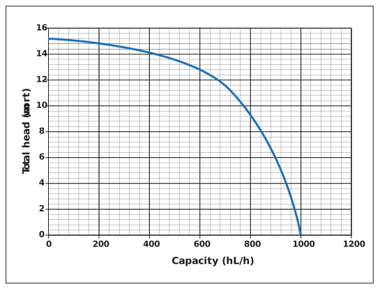
*** A centrifugal wort collection pump is used to pump three separate brews, of 500 hL each, into a multi-brew fermenter. The fermenter may be assumed to be a vertical cylinder of 4 m internal diameter. The characteristic curve for the pump is shown below.
a) What would be the initial flow rates that the pump would deliver for each of the three brews? (You may assume the suction head on the pump is zero, and that the only head on the discharge of the pump is that due to the hydrostatic head of the brews inside the fermenter).
b) What would be the three values of pumping power at the start of each brew transfer? Wort density is 1,065 kg/m³.
c) Explain why the flow rates during the transfer of each brew are neither constant nor the same?
d) If you wished the flow rate for each brew to be the same and constant, explain how adjusting the speed of the pump may achieve this?
Response:
a) Before we draw a simple sketch, let us determine what hydrostatic head would correspond to one brew? Each brew is 500 hL in volume, and we are told the fermenter is a vertical cylinder of 4 m inside diameter. Hence the volume of a brew, within the fermenter, would be given by:

Where h would be the vertical head that a brew would occupy. To determine h:


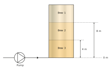
Each brew will create a 4 m head of wort in the fermenter. So, let us draw a simple sketch:
When considering the notation of brew numbers, do not get confused.
Brew 1 would enter an empty fermenter, whereas brew 2 would enter and have brew 1 above it and push it up the fermenter. This is the same for brew 3, which would have both brews 2 and 1 above it.
We can see that at the start of transferring brew 1, the fermenter would be empty and therefore a zero total head would be on the pump. Whereas on transferring brews 2 and 3 there would be initial heads of 4 and 8 m on the pump, respectively.
Let us now determine from the pump curve the corresponding capacity (flow rate delivered) by the pump at 0, 4 and 8 m total head. These capacity values are 1,000, 940 and 840 hL/h, respectively.
b) Pumping power is given by the product of total head and capacity:

At the start of each brew transfer, the total heads are 0, 4 and 8 m wort, at capacities of 1000, 940 and 840 hL/h, respectively. Therefore, the pumping power at the start of the transfer of brew 1 is:

A 0 W pumping power might seem strange, but do not forget that the pump is doing no work on the wort as there is no head on the discharge side of the pump. There would, of course, be some electrical power drawn to drive the motor and overcome inefficiencies.
The start of transfer of brew 2:

And for the start of transfer of brew 3:

c) The flow rate of each brew will neither be the same or constant during the transfer of the brew. As the hydrostatic head increases in the fermenter during filling, the operating point of the pump changes.
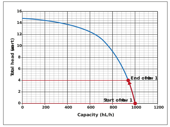
If we consider any one of the brews – let us take brew 1 – then the total head which the pump must work against during brew transfer is initially zero. This increases to 4 m of wort at the end of the transfer of brew 1. The operating point of the pump will rise up the pump curve, with an initial capacity of 1,000 hL/h and reducing to 940 hL/h at the end of brew transfer, as shown in the figure below. The same logic applies to brews 2 and 3.
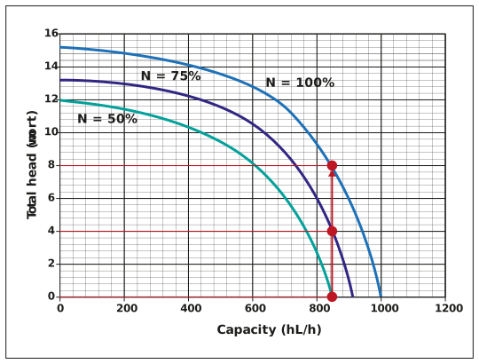
d) If we wished to have the same and constant flow rate for each brew then changing the speed of the pump, or more specifically the speed of the pump impeller, would influence the pump curve favourably. We should also consider the diagram below, which shows three pump curves where the impeller is running at 50%, 75% and 100% (as examples). The operating points at the start of each brew transfer are shown generating the same capacity of 840 hL/h. In reality, the pump would be gradually sped up, from 50% to 100%, so that the pump provides a steady flow rate of 840 hL/h throughout the transfer of all three brews.