
Lesson 8 - Control of Fluid Flow 1
This lesson will consider two main classifications of pumps: centrifugal and positive displacement. These will be introduced together, with aspects of their design and operation. The lesson will also pull together various fluid mechanics concepts from previous lessons, such as the Darcy-Weisbach equation and the use of loss-coefficient to calculate pressure drops in pipe systems. It will use this information to then size pumps for particular pipe systems.
Rotary Displacement Pumps
While reciprocating displacement pumps utilise a backward and forward motion to entrap and displace the liquid being pumped, rotary displacement pumps, as their name suggests, utilise a rotary motion to displace liquid. (Do not get confused with centrifugal pumps, which we have already discussed). Yes, they operate using a rotational motion but they do not entrap and displace liquid, which positive displacement pumps do. Let us now have a look at some common rotary displacement pump types
Rotary lobe pump
The rotary lobe pump has two drive shafts which are driven in opposing directions within a casing. Each shaft has an impeller fitted to its end, and the impeller is fitted with a series of lobes (think of your ear lobe for the shape), with the most popular design having three lobes – the tri-lobe pump – in the shape of a clover. The figure below shows a tri-lobe rotary pump.
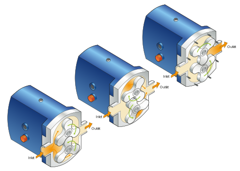
Figure: A tri-lobe rotary pump
In the above figure, the two sets of lobes can be seen rotating in opposite directions. The following points describe how the tri-lobe pump achieves a pumping action:
-
The spacing and timing of rotation of the lobes are such that when they rotate, they almost touch (a close clearance gap) together in the centre of the casing and also almost touch either side of the casing.
-
In the position shown above, where a pair of lobes are considered to be ‘meshed’ (or near one another), the rotation of the lobes creates a contained volume of liquid along the right-hand side of the casing wall. Further rotation sweeps the liquid towards the pump outlet.
-
The liquid does not pass through the centre of the pump between the lobes. The close clearance of the lobes ensures this.
-
As the contained liquid reaches the pump outlet, the lobes re-mesh thereby ensuring that the liquid does not flow in between the lobes. Instead, it is pumped out of the pump outlet.
-
Each lobe sweeps a volume of liquid through the pump sequentially and out of synchronisation with the other lobe.
The simple animation below shows the sequence of these operations.
Animation: A tri-lobe rotary pump
The tri-lobe pump offers the following characteristics:
-
It does not have any valves which make it easier to clean and sanitise effectively.
-
It is less effective at handling low viscosity liquids such as beer and wort. This is due to the clearance (gaps) between the lobes and the casing, which allows low viscosity liquid to escape from the swept volume along the casing wall.
-
Higher viscosity liquids, such as brewing syrups and yeast slurries, are particularly suitable for pumping as there is less of a tendency to escape from the swept volume (mentioned above).
The progressive cavity pump
These pumps are technically classed as progressive cavity pumps, but they are commonly known by several different names, e.g. screw pump, helix pump or mono pump.
The name ‘Mono’ is actually the name of a pump manufacturing company. Mono™ manufacture this type of pump, but as with a hoover or a xerox machine, the company’s name is often used to describe the type of pump rather than a specific manufacturer’s product.
The progressive cavity pump visually looks quite different from most other pumps in that it looks like a long length of pipe rather than a compact casing. Its rotor consists of a long helix that rotates eccentrically within a flexible stator tube which has helical grooves in its inner surface. Phew! There’s a lot going on in that description, so we will break it down with the help of a figure and the following description:
-
Rotor – a long helix, or spiral rotor.
-
Eccentric rotation – instead of merely rotating around a fixed centreline, the rotation is around an offset centreline. This gives it an eccentric rotation (eccentric is the opposite of concentric). An example of this is an eccentric ceiling fan which rotates with a ‘wobble’, instead of rotating completely true.
-
Flexible stator tube – this is often made of rubber or other flexible material and has grooves in the inner surface. The rotor helix rotates within the stator grooves.
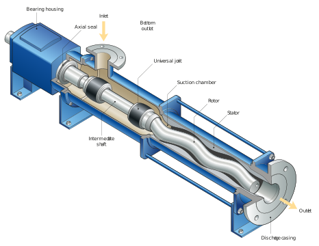
Figure: Progressive cavity pump schematic
The operational principles of a progressive cavity pump are often poorly understood. People often assume it is a simple screw rotating within a rubber tube, in a similar way as a screw conveyor or an Archimedean screw. These devices are similar but not the same and differ in an important way. The difference is how the progressive cavity pump manages to create a series of individual cavities through the eccentric rotation of its impeller within the grooved stator, and how it moves these cavities along the stator.
The progressive cavity pump offers the following characteristics:
-
It possesses no valves, which makes efficient cleaning possible. However, high-temperature sterilisation of the stator should be done cautiously with reference to the operating temperature of the stator material.
-
It is very effective for viscous liquids and slurries, such as mash slurries, yeast, trub and filter aid slurries, providing that sufficient liquid is present in the slurry to lubricate between the rotor and stator.
-
The pump must not run dry – this is an extension of the above point in that pumped liquid also lubricates the contact points between the pump rotor and stator.
Figure: Progressive cavity pump animation
Peristaltic pump
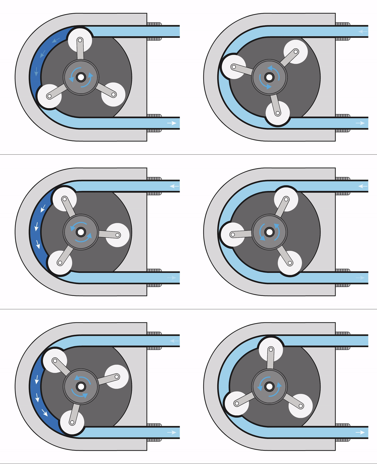
Peristaltic pumps are often called hose pumps or roller pumps, and the latter name gives a clue to the principle on which they operate, that is, as a pair or to be more precise, as a pair of rollers. They are used to pinch the outside of a flexible hose and push the liquid trapped between the rollers forward to the end of the pipe. The simple animation below shows this operation.
Animation: Peristaltic pump
In the animation above, a flexible hose arranged in a semicircle holds a liquid. A pair of rollers, at the end of a rotating rotor, sequentially pinch the hose and squeeze the liquid between the two pinch-points forward towards the outlet. Continued rotation of the rotor repeats the cycle, thereby pumping liquid through the pump.
The principle of operation of a peristaltic pump, called peristalsis, is something you are all closely involved with, although you may not be aware of it. It is how humans swallow food. In this case, the muscles surrounding the digestive tract rhythmically contract and relax to move a piece of chewed food through your digestive system.
Peristaltic pumps possess the following characteristics:
-
No valves are present which affords hygiene benefits. The pinch-points between the roller and the hose are normally sufficient, even when the rotor is stationary. This avoids back-flow through the pump and eliminates the need for a non-return valve.
-
The pump design is very hygienic as the liquid being pumped is not in direct contact with the pump itself, but is wholly contained with the flexible hose, so there are no concerns about surface finishes of rotors, stators, and seals etc.
-
Cleaning of the pump involves incorporating the cleaning of the flexible hose as part of a line clean. Care must be taken to ensure the pump rotates at the required line speed.
-
Relatively little slippage occurs, particularly if viscous liquids are used, so the flow rate can be accurately estimated by knowledge of the rotational speed of the rotor. This makes the pump well suited as a dosing pump or simply a known flow rate pump without the need to utilise a flow meter.
-
The pump is well suited to handling viscous liquids, (yeast) slurries, abrasive liquids or slurries, or aggressive liquids (e.g. acids and caustic) and to applications requiring accurately metered flows.
-
We often sees these pumps on a small-scale in laboratory situations as they are a convenient means to pump small quantities of liquid. Larger (industrial) scale versions are also available.
-
The hose is susceptible to wearing out and cracking/leaking.
-
The discharge from these pumps can pulse significantly. Increasing the number of rollers can reduce this pulsation but at the expense of wearing the hose out earlier.
- Vibration is an issue on larger units and bellows are fitted to both the inlet and outlet to isolate the pump’s vibrations from the mains system.
Positive displacement pumps operate on the principle of volume entrapment and displacement, where discrete volumes of liquid are (en)trapped and then mechanically displaced.
Positive displacement pumps can be classified by the manner in which the pump displaces the liquid, namely whether it does so using reciprocating displacement or via a rotary displacement.
We have covered some detail on different centrifugal and positive displacement pump types, and you will have seen that not only can they visually look very different from one another, but they can also operate on a diverse range of principles. This diversity also translates to different flow performance – the pressure they can generate whilst delivering a particular flow rate. It is important to be aware of this in selecting and specifying a pump for a particular application or changing the operation of an existing pump.
Let us now look at some specific performance aspects of centrifugal and positive displacement pumps.