
Lesson 8 - Control of Fluid Flow 1
This lesson will consider two main classifications of pumps: centrifugal and positive displacement. These will be introduced together, with aspects of their design and operation. The lesson will also pull together various fluid mechanics concepts from previous lessons, such as the Darcy-Weisbach equation and the use of loss-coefficient to calculate pressure drops in pipe systems. It will use this information to then size pumps for particular pipe systems.
Pump Mechanical Shaft Seals
A shaft seal is a device which allows a rotating shaft to be sealed against the stationary pump casing. This reduces or eliminates the leakage of liquid from the pump casing. It also limits the entry of air into the pump casing and hence the pumped liquid. The latter aspect is particularly important for many brewing product streams which are sensitive to oxygen.
A simple pump seal is the ‘stuffing box’, which is shown in the figure below. Within this, a sealing material (also termed packing) is packed into a gap between the pump casing and the driveshaft, through the action of a threaded gland. The gland is tightened sufficiently to squeeze packing onto the shaft to create a seal, but not too tightly to stop the shaft rotating. Such seals are not considered hygienic as the liquid being pumped will contaminate the packing material and cannot be easily cleaned out; hence they are more suitable for pumping of utility liquids, and not suitable for product pumping.
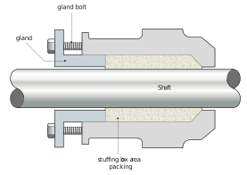
Figure: A stuffing box seal
Hygienic seals
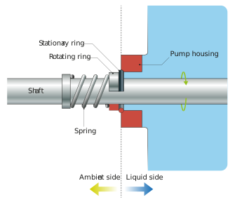
Figure: A hygienic pump seal
The figure below shows the shaft seal assembly from the outside of the pump. Sometimes shaft seals are lubricated by a trickle of water running through the outside of the seal.
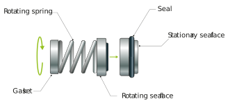
Figure: Spring assembly which forces the rotating seal component onto the stationary ring
Seal materials also need to be compatible with the liquid being pumped at both the operating temperature range of the pump when in service (i.e. pumping) and during cleaning.
Double water flush seals
Another type of seal used in brewing (particularly for hygienic wort applications) is a double water flush seal. Essentially this consists of two mechanical seals in series separated by a barrier fluid (commonly water). An example is shown in the figure below.
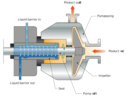
Figure: Double water flush seal
Single mechanical seals operate using the process fluid as a seal face lubricant, while double mechanical seals use the barrier fluid. This makes double mechanical seals ideal for hygienic applications such as wort transfer (this sticky liquid would not make an ideal lubricant). Constantly flushing the seal with water also eliminates any build-up of sugary liquid between the seal faces which would have been a haven for bacteria growth. It also prolongs the life of the seal itself.
Materials of construction
The materials used for the manufacture of the pump impeller and casing are dependent on the application. It is important that the pump is not corroded by the material being pumped and similarly, the pump materials should not contaminate the product being pumped. While it is common to check for corrosion resistance via corrosion charts (which are typically available from pump manufacturers) we must ensure the manufacturers have a clear understanding of the fluids to be handled including any suspended solids and other fluids that may be passing through the system e.g. CIP. In order to avoid tainting of beer flavour, stainless steel is usually used.
Hygienic considerations
We must ensure that the pump design matches the requirements of the liquid it is pumping and also its hygiene classification. Some liquids being pumped have very different hygiene requirements, e.g. cooling tower utility water vs bright beer.
If a hygienic design is required, there should be no crevices or excessive surface roughness of the impeller and casing to trap infection and make cleaning difficult. The centrifugal pump has the advantage that it can be hygienically designed and self-cleaning (as part of the cleaning of the line/pipe it is part of). Care needs to be taken that the seal assembly is not leaking and is not a source of infection.
Pump priming and self-priming pumps
To properly pump liquid, centrifugal pumps require the casing to be full of liquid before the pump is started. If the pump casing is partially or completely filled with gas or vapour, then the pump is said to be gas-bound. It will not clear itself of this gas, and it will not pump. Keeping the pump casing full of liquid can be achieved by ensuring that there is sufficient feed to the pump to fill the pump casing.
This is often done using gravity to feed the pump by locating the pump below the outlet of the vessel supplying liquid (one of the reasons why pumps are almost universally located on the floor below the level of brewing vessels).
During vessel CIP, it is important not only to flood the outlet main but to also empty the vessel completely during the various phases of cleaning. In order to achieve this, the CIP scavenge pump (this is located on the vessel outlet and is used to remove or scavenge the various cleaning liquids from the vessel) empties the vessel leaving no liquid which could be used to prime the pump. In order for the pump to easily prime itself, a self-priming design is often used. These work on two main principles:
- The first is to offset the position of the inlet so that the pump chamber always has enough liquid around the impeller to enable it to prime. This is shown in the figure below.
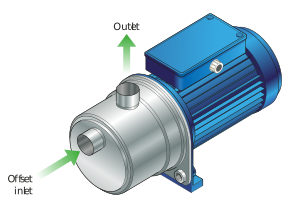
Figure: A self-priming pump with the outlet positioned at the top of the pump casing
- Another approach is to design a return from the pump outlet which feeds enough liquid back onto the impeller to enable the impeller to prime (see below).
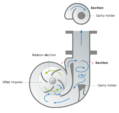
Figure: A self-priming pump showing the internal return of liquid back into the pump to prime the pump
Multistage pressure pump
For a particular impeller design, there is a maximum pressure that a single-stage impeller pump will develop. A sequence of booster pumps needs to be placed in series (which we will look at later in this unit) to raise the pressure above this. Taking that concept a step further, a multistage pump can be used, which has a series of impellers that feed the output of one impeller into the next – increasing the pressure. Such multistage pumps are available with up to sixteen sections, developing pressures up to 64 bar.
Above, we have covered some details of centrifugal pumps, their operating principle, and design. Now let us look at the other class of pumps – positive displacement pumps.