
Lesson 8 - Control of Fluid Flow 1
This lesson will consider two main classifications of pumps: centrifugal and positive displacement. These will be introduced together, with aspects of their design and operation. The lesson will also pull together various fluid mechanics concepts from previous lessons, such as the Darcy-Weisbach equation and the use of loss-coefficient to calculate pressure drops in pipe systems. It will use this information to then size pumps for particular pipe systems.
Centrifugal Pumps
Centrifugal pumps, also known as rotodynamic (rotational movement) pumps use the rotation of an electric motor driven shaft to exert forces on the liquid to transport it through the pump. The forces, as the name suggests, are centrifugal forces.
A good way to understand this is to think of our experiences as children on a rotating merry-go-round (or roundabout). Remember those? As they rotated faster, we would have felt a force (which was a centrifugal force) throwing us outwards. We had to hang on tighter to avoid being thrown off! With this understanding in mind, we can now examine this type of pump and the centrifugal forces, in more scientific detail.
Centrifugal forces
Centrifugal forces act radially outwards when a body rotates around an axis. Examples of centrifugal forces in action include:
-
When driving around a right-hand bend in your car, a centrifugal force pushes you to the left.
-
In athletics, a hammer or discus thrower rotates themselves using great strength to impart a centrifugal force to the hammer or discus, to allow it to be propelled radially outwards upon release.
-
In a centrifugal separator, such as those you see in a laboratory, a centrifugal force causes the denser objects within a suspension to be forced outwards (to the bottom of the test-tube).
How are these centrifugal forces generated within a centrifugal pump and imparted to the liquid being pumped? We will look at this now.
Centrifugal pump – operating principle
A centrifugal pump has an impeller mounted on the end of a horizontal shaft, which is typically driven by an electric motor. The impeller acts a little like the children’s merry-go-round mentioned above, in that the liquid is fed onto the centre of the rapidly rotating impeller and is thrown outwards with increased kinetic energy (see the figure below).
The impeller rotates within a stationary casing, which has a gradually increasing section with a single tangential outlet. The gradually increasing section reduces the velocity, and hence kinetic energy, of the liquid and converts this into pressure energy (remember Bernoulli’s equation?), such that the liquid leaving the pump has a higher pressure than the liquid entering. The shape of the casing slightly resembles a spiral seashell or a snail’s shell and is termed a volute. The image below illustrates some of these key aspects.
Volute is derived from the French volute or Latin volute meaning ‘roll’.
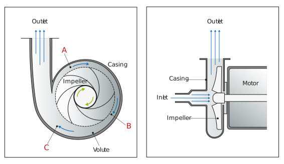
Figure: Two views of centrifugal pump showing key parts. Note the three sections, A, B, and C across the pump which are increasing in flow area
In a brewery or maltings, the centrifugal pump is by far the most common type of pump, particularly for pumping utility liquids. This is due to the many advantages and very few disadvantages it possesses:
Advantages
-
They are readily available, cheap, and adaptable.
-
They are simple in construction, reliable, and capable of a wide range of operations such as product and utility fluid pumping.
-
They give a steady delivery flow rate.
-
They can pump liquids with a broad range of properties, including liquids with high levels of particulates within them.
-
The discharge valve of a centrifugal pump can be fully closed (termed dead-ending), and the pump will safely churn the liquid around within the impeller, for short amounts of time, generating relatively small amounts of heat.
-
They have no internal valves and may be made from a range of materials capable of dealing with corrosive liquids.
-
For a given flow rate of liquid, the centrifugal pump is usually less bulky than a positive displacement pump, so the footprint space it occupies is less.
- They can be directly coupled to the motor which avoids an expensive gearbox.
Disadvantages
-
They operate with high rotational speed and therefore produce high shear rate levels, which may be damaging to certain liquids which are shear sensitive.
-
They are relatively limited in the delivery pressure they can generate (typically 1-8 bar or 100 - 800 kPa). However, multi-stage pumps (a number of pumps in series) can increase this pressure, with considerable expense and complexity but are essential in certain applications e.g. boiler water feed pumps. A secondary booster pump can also be used to overcome this pressure limitation (we will consider these later).
-
They are inappropriate for metering applications (measured delivery of known quantities of liquid) as the pump will deliver a range of flow rates depending on the pressure applied to the discharge of the pump (we will look at this in more detail later in this lesson).
-
The pump can only operate with a high efficiency over a relatively narrow band of delivery flow rate.
-
A non-return valve (or system) is required to stop liquid running back through the pump impeller when it is stationary.
Earlier, we discussed the impeller of a centrifugal pump and the role it played in imparting kinetic energy to the liquid by throwing it radially outwards into the casing. We will now examine the impeller design in more detail, with specific reference to brewing product liquids.