
Lesson 6 - Mashing Technology
Mash Agitation
Thinking back to our rudimentary mashing process with no in-line pre-masher and using paddles to mix the mash, we can easily see that this is not effective mash agitation. In this section, we will describe how effective mash agitation is achieved. Effective mash agitation is essential for successful decoction and single-vessel temperature-programmed mashing. Like pre-mashing, the technology used has evolved as our understanding of the science of mashing has improved.
What do we need from our mash agitation? It should:
-
Provide a uniform (homogenous) mash
-
Prevent overheating of the mash close to the point of heating
-
Minimise fouling on the heating surfaces
-
Minimise oxygen pick-up
-
Provide required access to substrates for hydrolytic enzymes
-
Minimise shear forces on mash
-
Assist in mash transfer
Effective agitation
If an in-line pre-masher that delivers mash from above is used, the first task of the agitator is to assist the pre-masher with grist hydration. This is achieved simply by stirring the mash to ensure the complete mixing of particles and liquid. All mixing of the mash helps ensure that enzymes have increased opportunities to bind to substrates and catalyse their hydrolysis. There is, however, no improvement in extract recovery with more vigorous or intensive mixing beyond a certain point. Also, excessive agitation, even at low shear, reduces mash particle size, which hampers wort separation.
Perhaps the most important role of the agitator is to assist in effective and even heat transfer to the mash. Properly designed agitators push the mash down onto the base of the MCV, across the bottom heating surface, then up the side heating surfaces. The figure below shows the correct agitation pattern.
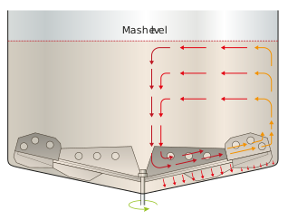
Figure: Pattern of correct mash agitation
This movement across the heating surfaces creates localised turbulence which helps transfer heat and reduces fouling on the heating surfaces. The movement and mixing of the mash also help distribute the heat evenly, preventing overheating in parts of the mash.
Although the mash needs to move swiftly over the heating surfaces, movement needs to be gentle to minimise shear forces and to prevent the formation of vortices and swirling that draw air into the mash. It is important to understand that even in the absence of whirlpooling, the mash is turning over, so all of the mash is exposed to the atmosphere in the vessel headspace for a period of time. This is why it is important to maintain an oxygen-free atmosphere in the vessel. Mash oxygenation aside, whirlpooling is undesirable because it reduces flow across the heating surface and heat transfer across the mash.
Good mash mixing is said to fold the mash, like folding in ingredients when baking, rather than spinning it like in a food processor.
Shear forces in mashing
Well-designed mashing technology minimises shear forces on the mash. Shear forces exist wherever flows of different velocities or pressures are adjacent to each other. This can be at the tip or leading edge of the agitator, along the vane of a pump impeller or around a bend in the pipework.
Shear is when an object is subject to forces acting in opposite directions. For example, the chimney on a ship sailing into a headwind experiences the force of the ship moving forward at its base and the wind blowing in the opposite direction at its leading edge. If the wind is strong enough, the shear force on the chimney will be sufficient for it to bend and eventually snap. The same happens to a grist particle and even a β-glucan molecule in mashing.
Shear forces increase the viscosity of β-glucans by encouraging cross-linking. They are also thought to form gels of β-glucans and proteins, thus increasing wort viscosity and reducing filterability. More significantly, shearing also reduces particle size in the mash. Both high viscosity and reduced particle size work together to make the wort separation slower and less consistent. We will cover this in detail in the Wort Separation unit.
Agitator design
The first agitators were also called propellors because they looked similar to the things that propel small aeroplanes. They were a lot shorter than modern agitators and ran at much higher speeds. If we compare this design to the criteria we set out earlier, we can see they were not ideal for the job.
Modern agitators come in a wide range of shapes and designs and are continually evolving. Let’s look at some common design elements.
-
Width – as they rotate, agitators should cover the majority of the area of the base of the vessel. Most are at least 85% of the diameter of the vessel in width. If shorter agitators are used, baffles on the sides of the vessels are required to help mix the mash.
-
Perforations – perforations (or, in fact, pretty big circular holes) in the agitator blade allow some mash to flow through. This prevents the solids in the mash from building up on the agitator surface and being pushed around the vessel with the rotation of the blades. They also help mixing. The agitator in the figure below has perforations.
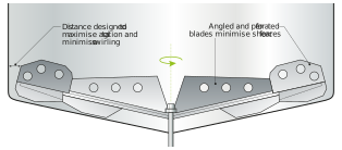
Figure: Modern mash agitator
-
Angled blades – most blades are angled down along the section from the centre out to help move the mash across the base heater and angled up towards the tip to help move the mash up the sidewalls of the vessel. The angles in the centre of the agitator should allow the mash to fall over the agitator rather than being pushed by it (or feature the perforations detailed above).
-
Optimised height – the distance from the agitator to the heating surface is set to ensure the mash moves across the heating surface in a way that maximises heat transfer and minimises fouling.
-
Central mixing – the zone in the centre of the base of the vessel where most agitator shafts are located can be a dead zone. Agitators should be designed to ensure this area is also mixed as the agitator rotates. Some agitators have small blades that mix the mash in this area.
Some MCVs have baffles on the sidewalls to prevent the mash from rotating as it is agitated. With larger vessel sizes, there is a greater tendency for the mash to be pushed along by the agitator, so these are more often fitted in larger vessels. Baffles can increase shear forces and are sometimes difficult to clean effectively, but vessels are available with baffles that do not suffer from these problems.
Not all agitators have all these features, but whatever combination is used, the manufacturers will claim that theirs do a wonderful job! The key is to ensure the agitator is correct for the vessel shape, heating area and pre-mashing technology.
Here are some links to allow you to research further. Please note, this is for illustrative purposes only and is not a recommendation or endorsement of the supplier’s product.
https://www.gea.com/en/binaries/service-agitator-2.0_tcm11-56855.pdf
https://braukon.de/en/produkt/braukon-gentlemix-en/
https://www.ziemann-holvrieka.com/en/component/edocman/4-colibri-mash-agitator/download
https://www.briggsplc.com/wp-content/uploads/technical-papers/IBD-DCCC-BHHeat-Jan-2017-Briggs.pdf
https://www.steinecker.com/media/downloads/shakesbeer_en.pdf
https://zipbier.com/ziptech-smart-systems-turnkey-breweries-from-250-to-5000-liters/
There are two agitators that feature slightly unusual design elements. The Briggs agitator is offset in the vessel by 5% of the diameter. The MCV itself is tilted, and the central section of the agitator arms is cylindrical rather than angled.
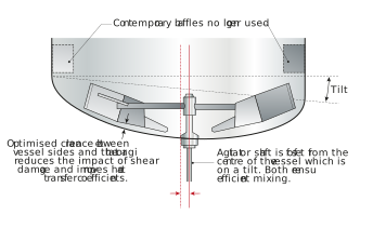
Figure: Briggs agitator and MCV
The Ziemann Holvrieka Colibri agitator has a flat-faced perforated blade extending from the centre to the vessel edge following the contour of the base. These are designed to move mash over the base heating plates while mixing. At the ends of this blade are vertical cylindrical sections. These are designed to move mash and mix mash at the walls of the tank (acting like an anchor agitator) and keep the mash moving across the wall heating jackets. This is said to reduce fouling on the side wall heating jackets and hence reduce CIP frequency. At the top of these sections are spiral sections that cut through the top and middle of the mash to aid mixing and heat transfer. Finally, halfway up the tank is a transverse set of angled blades designed to homogenise the mash further. The figure below shows the Colibri agitator without the transverse blades. With such a large agitator blade, the motor required for the Colibri is comparatively large as is the energy is uses.
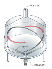
Figure: The Ziemann Holvrieka Colibri agitator
Agitator operation
High agitator speeds maximise pretty much everything we need to minimise! They increase shear, oxygen pick-up and above a certain level, mix the mash less effectively. They are also a waste of energy.
Agitator tip speeds should be as low as possible without compromising heat transfer and heating surface cleanliness.
Tip speeds as low as < 1 m/s have been recommended with maximum tip speeds of 3.0 m/s for hammer milled grist, 3.8 m/s for roller milled grist, and 4.3 m/s for coarse grits also suggested.
Agitators are driven by large motors controlled by variable speed drives (VSD). VSDs allow the brewhouse controller (computer or person) to change the speed of the agitator to achieve the mixing and heat transfer requirements of the mashing programme. VSDs also allow agitators to start at a very slow speed and then ramp up, meaning the motor draws less current and consumes less energy.
Agitators are controlled according to the mashing programme, and these vary from brewhouse to brewhouse. Higher speeds are used when mashing in (after the agitator is submerged) and heating the mash. Lower speeds are used during temperature stands. Brewhouse software will ensure that the agitators continue to run after the jacket heating is closed to ensure the residual heat in the jackets can be dispersed throughout the mash. In some MCVs, the agitators are turned off during stands, while in others, they are maintained at low speeds to prevent the mash from settling and becoming less homogenous. In decoction, mashing agitators are stopped before decoction to allow the mash particles to settle to produce a thick mash.
Mash agitation is run at higher speeds before mash transfer/mashing out to ensure the mash is as homogeneous as possible but slowed as the mash becomes shallower. They are stopped as soon as they are uncovered to avoid oxidation.
Some agitators can be run in reverse during mashing in to help with hydration.
Some mashing vessels feature ultrasonic vibrators to work alongside the agitator. These are designed to help mixing, drive off entrained air and reduce total mashing time by increasing the number of substrate-enzyme interactions.
Whatever design and control are used for our agitation, it must work effectively with our next technology, mash heating.