
Lesson 10 - Jacketed Vessels
This lesson explores another type of common heat transfer equipment used in brewing, namely jacketed vessels. It investigates the application, specifications, and the operating conditions of these exchangers. It also looks at their design and sizing considerations.
Heat Transfer Within a Jacketed Vessel
In this lesson so far, we have explored a number of features of jacketed vessels that make them ideally suited for heat transfer applications. In this section, we will look more closely at how heat is transferred within a jacketed vessel.
Let’s begin by looking at the cooling process that happens in a typical fermentation jacketed vessel (as shown in the figure below).
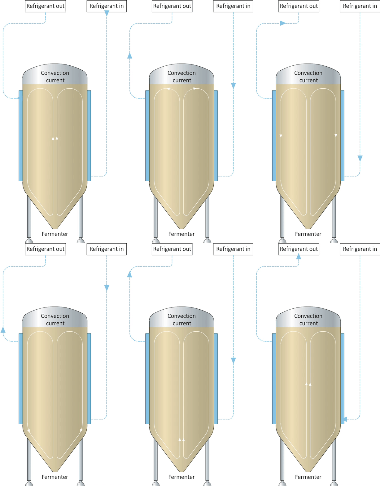
Figure: Transfer of heat during chill back of a fermentation vessel
During fermentation, heat is generated. To keep the fermenting beer at a constant temperature, this heat of fermentation must be removed. A refrigerant, such as liquid ammonia, flows into and fills the jacket. Heat is transferred from the warmer beer inside the vessel and through the vessel wall into the colder ammonia. The heat generated from the fermentation is removed, and the ammonia evaporates and leaves the jacket as a gas.
Once the fermentation is complete, the beer must be chilled. The beer in the fermentation vessel must be cooled from a fermentation temperature of, for example, 15°C down to 4°C. Again, heat is transferred from the warmer beer inside the vessel, through the vessel wall and into the colder ammonia. But in this instance, the beer cools down as the ammonia evaporates.
We can say the following about the heat transfer mechanisms in jacketed vessels:
-
In vessels where there is no forced agitation (such as a fermentation vessel), the heat transfer mechanism is a combination of natural convection (from the beer to the vessel wall) and conduction (through the wall).
-
In vessels that are mechanically agitated (for example a mash vessel), the heat transfer mechanism will be a combination of forced convection (from the mash to the vessel wall) and conduction (through the wall).
-
When the temperature difference between the product and utility fluid remains constant over time (as during the fermentation step in a fermentation vessel ), heat transfer is steady state.
-
When the temperature difference between the product and utility fluid changes over time (e.g. during the cool down step in a fermentation vessel), heat transfer is unsteady state.
Unsteady heat transfer
In the lesson on Radiation and Combined, we encountered the following equation, which we can use to calculate the heat transfer through a multi-layer system:

This equation works well during steady state heat transfer. However, for unsteady state heat transfer an integration of this above equation that takes account of the changing temperature difference over time is preferred. This is represented as follows:

Where
Ts is utility fluid temperature (°C)
T1 is the initial temperature of the vessel contents (°C)
T2 is the final temperature of the vessel contents (°C)
M is the mass of the liquid being heated (kg)
Cp is the specific heat of the fluid being heated
A is the total heat exchanger surface area measured in m2
U is the overall heat transfer coefficient measured in Wm-2 K-1
t is the time (sec)
This equation applies when the utility fluid is at a constant temperature (e.g. undergoing a phase change). When the utility fluid undergoes a change in temperature, the calculation is far more complex. In cases where the temperature change is relatively small, such as in brewing applications, a good approximation can be made by using the mean temperature of the utility fluid.
Furthermore, this equation assumes that all the energy transferred to or from the utility fluid is used to change the temperature of the product. It also assumes that no heat is lost to the environment. Insulating the vessel can ensure that this heat loss is kept to a minimum.
In unsteady state heat transfer, because the beer temperature is changing, the heat transfer coefficient is changing too. In practice, however, we assume an average value for the heat transfer coefficient to simplify the calculation.
Now that you are more familiar with the principles of unsteady state heat transfer with regard to jacketed vessels, let’s look at how this and other heat transfer equations can be used to size jacketed vessels.