
Lesson 10 - Jacketed Vessels
This lesson explores another type of common heat transfer equipment used in brewing, namely jacketed vessels. It investigates the application, specifications, and the operating conditions of these exchangers. It also looks at their design and sizing considerations.
Features of Jacketed Vessels
While the jacket type may vary, there are some features that can be applied to all jacketed vessels. These features will ensure optimum heat transfer and control. In the next section, we will look at some common characteristics of jacketed vessels.
Multiple jackets
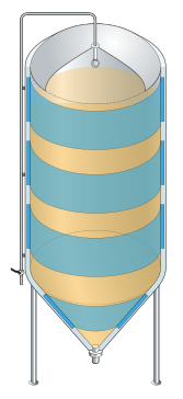
Figure: Vessels with multiple jackets
As we can see in the figure above, vessels, particularly large ones, can have multiple jackets. Multiple jackets offer two major benefits:
-
They allow the utility fluid to be controlled to certain sections of the jacket at certain times. It is not uncommon for brewery fermentation vessels to have as many as four separate cooling jackets, each one separately controlled. This is explained further later on in this lesson.
-
Furthermore, they can achieve high utility fluid flow rates while minimising pressure drop across the jacket. This is because rather than the utility fluid flowing through one large jacket the entire length of the vessel, it splits and flows through two shorter jackets, each half the length of the vessel.
Insulation
When you look at a jacketed vessel in a brewery, it does not look like the vessels in the figure above. This is because, more often than not, jacketed vessels are insulated.
An insulated vessel experiences about 25 times less heat loss/gain.
This insulation ensures that as little heat as possible is lost to or gained from the outer jacket wall, and that all the heat is transferred inwards to the vessel or outwards to the utility fluid. If a vessel is insulated, a thin sheet of stainless steel or aluminium cladding is wrapped around the lagged vessel to protect the insulating material.
Jacket position
As shown in the figure below, the jacket must be positioned so that it is always physically below the product liquid level. If the vessel is being used for heating, this will ensure that there is no unnecessary burn-on of product to the vessel wall. If the vessel is used for cooling, it will ensure that no ice forms on the vessel walls.
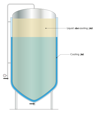
Figure: Jacket position relative to liquid level
If heating or cooling is required when the vessel is partially full, this can be achieved by splitting the jackets and controlling each jacket as the vessel fills or empties.
Jacket vent
If the utility fluid in the jacket is a gas (e.g. steam), and the steam is contaminated by other non-condensable gases (e.g. air), then this air will collect in the jacket and reduce the rate of heat transfer. This is due to the poor thermal properties of air. In jacketed vessels, this is overcome by installing a small air remover vent at the top of the vessel (as shown in the figure below). This vent can be manually opened routinely, or it can be automated to pulse open and closed at a predefined frequency.
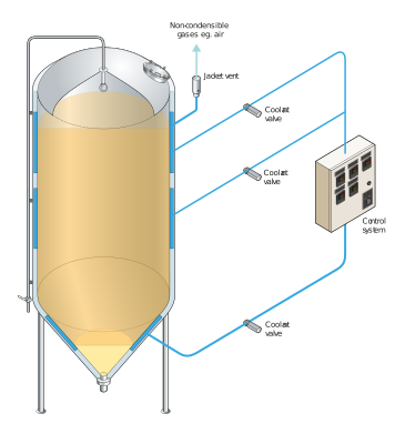
Figure: Jacket vent valve to purge non-condensables
So far, we’ve learned about the various types of jacketed vessels, their components, and their key features. With this knowledge, we can now better explore how heat is transferred within jacketed vessels.