
Lesson 10 - Jacketed Vessels
This lesson explores another type of common heat transfer equipment used in brewing, namely jacketed vessels. It investigates the application, specifications, and the operating conditions of these exchangers. It also looks at their design and sizing considerations.
Jacketed Vessels: Design Considerations
As with all heat exchangers, jacketed vessels are designed to maximise heat transfer. In this section, we will look at the key features of jacketed vessels and explore how these both enhance and limit the heat transfer rate.
In the Heat Exchangers lesson, we learned that heat exchanger design is influenced by three key variables, namely:
-
Heat transfer surface area (A)
-
Overall heat transfer coefficient (U)
-
Temperature driving force (∆T)
Let’s look at some of the key features of jacketed vessels and consider how their design can be optimised to achieve maximum heat transfer while also being reliable and affordable.
Heat transfer surface area
The heat transfer area in a jacketed vessel is the surface area of the vessel wall that is covered by the jacket. In the figure below, the heat transfer area is the section of the vessel shown in red.
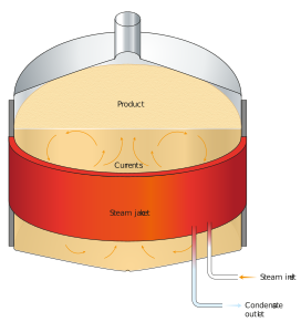
Figure: Heat transfer surface area of a jacketed vessel
In the above figure, we can see that the available heat transfer area is limited by the size and dimension of the vessel. The heat transfer area can be increased by increasing the height to diameter ratio. However, this is limited by the space available and the cost of manufacturing and transporting the vessel.
Typical height:diameter ratios range from 2:1 to 4:1.
Because the surface area is limited within jacketed vessels, if a greater heat transfer rate is required, this must be achieved by increasing the other two inputs for heat transfer, namely the overall heat transfer coefficient and/or the temperature driving force. If doing this still does not achieve the required heat transfer rate, then other technologies for vessel heating, such as an external heat exchanger, can be considered.
Overall heat transfer coefficient
In jacketed vessels, the overall heat transfer coefficient refers to how well heat is conducted from the product fluid inside the vessel, to the vessel wall surface, through the vessel wall, and into the bulk of the utility fluid. This is influenced by:
-
Product and utility fluid velocities
-
Degree of fouling/scale on the heating surface
-
Vessel wall thickness
-
Material used for the vessel wall
If you recall from the lesson on Radiation and Combined heat transfer the overall heat transfer coefficient is influenced by two major factors; convective film coefficients and conductive resistance. The first of these has a far greater influence on the overall heat transfer coefficient than the second. In practice, this means that the biggest influence on the overall heat transfer coefficient is the product and/or utility fluid velocities and the degree of fouling/scale.
Let’s take a look at each of these in more detail.
1. Product fluid velocities
When a vessel is heated or cooled, the fluid inside the vessel will still move – even if there is no agitation. This type of movement is known as ‘natural convection’.
-
In natural convection, the fluid moves due to a difference in density (resulting from the temperature difference through the vessel).
-
Movement by natural convection is relatively slow, which means that the fluid velocity of the product inside the vessel is low.
-
This results in low heat transfer coefficients.
-
When a vessel is agitated, the movement of the fluid occurs through forced convection.
-
Movement by forced convection has a much higher velocity.
-
Forced convection improves the heat transfer coefficient, reduces the rate of fouling, and increases the temperature driving force.
Because there is no equipment inside the vessel, there are no limitations on the type or design of agitator that is used in a jacketed vessel.
To learn more about different agitator designs, visit the websites linked below. Note, this is for illustrative purposes only and is not a recommendation or endorsement of the supplier’s product.
http://www.thermopedia.com/content/549/
https://www.slideshare.net/vshroff/agitator-design-and-selection
2. Utility fluid velocities
Generally, the velocity of the utility fluid through the jacket is low compared to other types of heat exchangers. In the next section, we will explore how different jacket designs try to improve the velocity of the utility fluid.
If the utility fluid is changing phase, the velocity of the fluid is less critical for achieving good heat transfer rates. This is why condensing steam or evaporating ammonia are both popular choices for utility fluids in jacketed vessels.
As with other heat exchangers, a designer needs to balance the benefits of high turbulence against the cost of a high pressure drop through the vessel jackets.
3. Fouling and scale
As with inline heat exchangers, typical values for the overall heat transfer coefficient in jacketed vessels will include an allowance for the scale and fouling that will typically occur during a normal operation.
So, a new vessel with no fouling will initially exceed its performance specification. However, as foul or scale builds up on the vessel wall, the heat transfer performance will drop and it will gradually take longer and longer to achieve the required temperature change in the vessel. This decline will continue until the duration of heat up / cool down exceeds the design specification, at which time the vessel will need to be cleaned.
Because the heat transfer surface is the vessel wall, it is easy to clean using the cleaning system of the vessel.
In contrast, it is virtually impossible to clean the jacket side of a jacketed vessel. The utility fluid used should be non-fouling or non-scaling, and its quality must be regularly monitored.
4. Vessel wall thickness
As we learned in the previous Heat Exchangers lesson, reducing the thickness of the heat transfer plate (in this instance the vessel wall) improves the overall heat transfer coefficient. However, in jacketed vessels, first and foremost, the vessel wall must be sufficiently strong to support the vessel and its contents under a full load. A thin vessel wall can give good heat transfer, but it can compromise the vessel’s strength.
5. Material of construction
As with other heat exchangers used in brewing, the first choice for the jacketed vessel material is stainless steel because it is easy to clean, strong, and has an acceptable heat conductivity.
Temperature driving force
In jacketed vessels, the temperature driving force, ΔT, is defined as the difference in temperature between the product fluid inside the vessel, and the temperature of the utility fluid.
Agitation of the product fluid inside the vessel ensures uniform temperature of the fluid, which in turn improves the temperature driving force.
The temperature driving force can also be increased by increasing (in the case of heating) or decreasing (in the case of cooling) the utility fluid temperature. This must be balanced off against the risk of increased fouling (in the case of heating) or freezing the product (in the case of cooling). Care must also be taken if the product fluid is heat sensitive.
As you will recall in the Lesson on Heat Exchangers we spoke about another ∆T, the change in temperature of each single fluid. In jacketed vessels this is the change in temperature of the utility fluid between when it enters and leaves the jacketed vessel or the product fluid between the start and end of the process. This is not a driving force for heat transfer.
We have reviewed some of the key heat transfer principles and looked at how they should be considered when designing jacketed vessels. In the next few pages, we will look at the three different types of jacketed vessels found in breweries.