
Lesson 4 - Gas Transfer
This lesson focuses on transferring gases into and out of solution. It looks in particular at carbon dioxide dissolution in water and beer, and explores how to manipulate pressure, temperature, and gas composition to influence the saturated gas concentration (as well as the rate of gas transfer). It also looks at some tabulated data that are widely used in the industry. The lesson concludes by describing gas transfer technology.
Gas Transfer Technology
The design and operation of gas transfer technology can be illustrated with some common examples. This is not an exhaustive list as the marketplace is continually coming up with new technology.
The process of dissolving a gas in a liquid, termed dissolution, is helped by several factors, as we’ve discussed, at length, previously.
Four key factors which promote dissolution and gas transfer rates are:
Low liquid temperature (increased equilibrium concentration CE). (Remember too that Henry’s constant is temperature dependant.)
Higher gas pressures (increased equilibrium concentration CE).
Increased turbulence between the gas and liquid phases (enhanced mass transfer coefficient kL).
Increased gas phase surface area, A, or specific surface area A/V (denoted ‘a’).
Let’s keep these factors in mind and look now at some common gas transfer technologies.
The lance
Perhaps the simplest of all gas transfer devices is the lance (sometimes called a nozzle). As its name suggests, it is an open-ended piece of pipe, which sometimes has a reducing diameter at its end (which is placed within a vessel for in-vessel batch dissolution). Gas is introduced through the lance and a bubble stream is produced at the end of the lance, thereby increasing the specific surface area for gas transfer.
The simple design of the lance makes it very suitable for cleaning as it does not have any fine holes which can present a cleaning challenge.
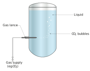
Figure: Gas lance in operation
The sintered ‘stone’
Sintering is a process whereby metal or ceramic particles are pressed into a shape then heated to just below their fusion point. Partial fusion takes place, to give a mechanically strong yet porous material, with a pore size of typically a few microns. For gas diffusion, the sintered material is typically made into a cylindrical shape, often referred to as a ‘candle’. The effect of passing gas through the candle immersed in a liquid is the formation of very many fine bubbles which significantly increases the specific surface area (interfacial area) ‘a’, enhancing the gas transfer rate. You may be more familiar with ceramic sintered air diffusers in a fish tank.
One downside of the sintered diffuser is its tendency to block as the pores are very small, so gas filters are required upstream as well as regular cleaning of the diffuser, which is typically performed by removing the stone and cleaning by hand.
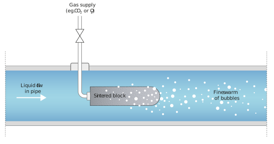
Figure: Sinter in line (also applicable in a tank)
Venturi carbonator
The figures below show the external view of a venturi carbonator and a schematic of the inside and its principle of operation.
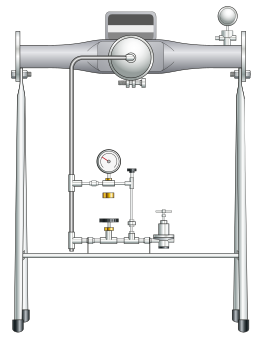
Figure: External view of a Wittemann venturi carbonator
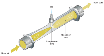
Figure: Section through a venturi carbonator
The venturi carbonator consists of a section with a reduced throat area – termed a venturi – which accelerates the liquid, thereby reducing its pressure (remind yourself of Bernoulli’s equation if required). At the narrowest part of the venturi, CO2 is injected as a bubble stream. The mixed liquid and gas stream flows through the region of increasing area, which is highly turbulent. Also, in this region, the pressure is increasing. Both of these factors aid gas transfer i.e. dissolution.
The venturi – a restricted section of pipe – is named after Giovanni Venturi (1746-1822) an Italian physicist and science historian. In addition to first discovering the effect on a flow of passing through a restricted section of pipe, he is also credited with being one of the first historians to draw attention to Leonardo da Vinci as not just a great artist, but as a scientist too. He clearly had a good eye for detail…
Location of gas transfer technology
As we discussed above, the use of pressure, temperature, turbulence, and interfacial surface area can enhance gas transfer rates in a gas transfer technology, however, the location of the selected technology can also utilise some of the parameters in enhancing gas dissolution.
For example, a wort aeration point would be located immediately after the wort cooler, where the temperature is low (lower than hot wort!) and the pressure is high as wort transfer line pressure losses have not occurred. Often, an inline mixer (a section of pipe fitted with an internal helix, or screw-shaped element, which promotes turbulence) is incorporated after the injection point to create turbulence and therefore aids solution.
When carbonating beer, the selection of an injection point is a compromise between temperature and turbulence/mixing. For example, if injection is made immediately before a plate-type beer chiller, the turbulence through the chiller could increase the transfer rate (although it may affect heat transfer effectiveness), but the drop in temperature post chiller will help gas solution.