
Lesson 12 - Control of Fluid Flow 3
This lesson will consider valve technology, which is used to control fluid flow. It will cover the control functions of on-off, and modulating flow control, together with a description of the various valve types which can achieve these functions. The lesson will conclude with thoughts on the issue of managing valve leakage to avoid cross-stream contamination.
Point of Reflection – Reconvene
Welcome back. So, what were your thoughts?
In all likelihood, you will probably have produced a variety of ideas, but let us consider a couple of concepts which you may have thought of:
-
Disconnecting the pipe – perhaps this seems too simple, but if a leak were to occur from one side of the valve or the other, its role in contamination would be greatly reduced, if not eliminated, if the valve was not connected to the pipe (as shown in the figure below). In this case, one end of the pipe has been disconnected, and if the valve passes, then liquid A would presumably drip onto the floor, which might not be too convenient, but it would not contaminate liquid B in the right-hand pipe.
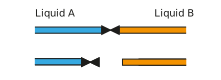
There is the slight inconvenience at the end of the pipe containing liquid B. What is going to stop liquid B pouring out? We quickly need to add another valve to the pipe.

This conveniently leads us to a second leak protection concept:
-
Doubling up the protection – does it make sense to have a set of double valves in series so that each valve can act as a back-up valve to the other? In this way, with luck and some favourable statistics, we would improve our chances of it being very unlikely that both valves would leak at the same time and thereby contaminate both liquids. If this were the case, we could reinsert the missing bit of pipe. This could look like the following, with an inter-valve section of pipe, into which any leak would gather.

But there are three things wrong with this set-up:
-
What happens when the inter-valve leakage space gets full due to leakage?
-
What happens when we want to transfer liquid through the valve/s, by opening them both? Won’t the leaked liquid contaminate this stream?
-
How would we know there was a leak so we could fix the root cause of the leak?
These issues are resolved with the final concept:
-
Direct the inter-valve leakage space to drain – why do we not (instead of leaving the inter-valve leakage space sealed between both valves), create a free-flow path for it out of the pipe? In this way, there would be no build-up of leaked liquid which would reduce the contamination potential. Also, by running this leakage path to drain, or on the floor near a drain, we could visually determine if either valve is leaking.
The concept of using a set of double valves, with a defined inter-valve leakage space and drain line is commonly used in the process to offer protection against leakage. Let us look at this in more detail and see how it can be achieved in practice.
Double block and bleed for leakage protection
The concept, as we worked out above, is to use a pair (or double valves) of valves to block the flow whilst also creating an inter-valve leakage space and allowing this space to flow (or bleed) to a drain line. This can be produced using three valves arranged, as shown in the diagram below. Valves V1 and V2 are the double block valves, and valve V3 is the leakage space drain valve. The drain line tends to be a much smaller diameter than the main pipeline as the expectation is that any leak will be small.
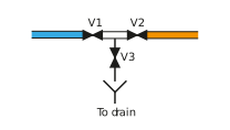
Figure: Double block and bleed valve array
In practice, V1 and V2 act together, and V3 acts in opposition to them. If flow is required through the pipeline, then V3 is closed and V1 and V2 are opened. Closing V3 ensures that the flow does not run to the drain when V1 and V2 are open. If V3 leaks, then the drain line will run, and a manual inspection will pick this up.
If the line is required to be closed, then V1 and V2 are closed, and V3 is opened. Thereafter, if any leakage from the upstream or downstream sides occurs through V1 or V2, then the leak will not pass through and instead be run to drain.
Care must be taken to clean the leakage space and the drain line properly during cleaning – manually or clean-in-place.
In practice, the double valves can be two separate valves installed close together or they can be purchased as a single valve unit with two valve seats present. The latter case is often termed a mixproof double-seat valve and is an interesting geometric solution to ensuring that two streams do not mix. Let us have a look at this in the next section.
Mixproof double-seat valve
The figure below shows the geometry of a mixproof double-seat valve. In this case, the valve separates two streams of liquid to be separately controlled whilst avoiding cross-contamination between the liquids.
The valve is a directional valve, which can direct flow along either line 1 or line 2 uninterrupted, or conversely allow flow from line 1 to line 2, and vice versa. So, for instance, you could transport wort and rough beer in lines 1 and 2 respectively, safely into and out of a fermentation cellar, whilst also allowing clean-in-place of either of these lines when the other line has wort/beer in it.
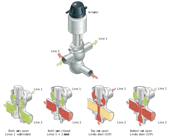
Figure: A mixproof double-seat valve
The valve consists of two independently controlled valve elements, shown in green and blue, respectively, which seat in two places: the lower surface of line 1 and the upper surface of line 2.
This is why it is called the double-seat valve.
Between these two valve elements is a leakage chamber which runs to an atmospheric drain through the hollow body of the second valve stem (we did mention it is an interesting geometric solution to the problem!). So, if either valve passes through its seat, the leak will run to drain, rather than try and force itself through the other seat.
Cleaning of the valve seat and the leakage space can be achieved during CIP by using ‘seat-lifting’ technology in which a valve would be automatically lifted for a short period during CIP of that line (e.g. CIP of line 1). This then allows the CIP solution to clean seat 1 and the leakage chamber, and then run to drain. If you are standing next to such a valve during CIP when the seat is cleaned, you will probably think the valve is defective and leaking as you will see liquid run out onto the floor (or on your safety shoes if you are unlucky!). All is good – just a seat clean in progress!