
Lesson 4 - Wort Separation Technology
This lesson deals with wort separation technology. The variables of Darcy’s Law are re-visited, to demonstrate how they influence the design of the lauter tun, mash tun, and mash filter. The key design features and control methods of these wort separation devices are identified. Typical operational steps and times are also established for each device.
Mash Filter Design and Operation
The mash filter design is very different from our two ‘tuns’ and is also much faster. We will now find out why.
Table: Design and operational parameters for the mash filter for 10 t grist
|
|
Lauter Tun |
Mash Tun |
Mash Filter |
|
|
|
Tun diameter (m) |
8 |
5 |
20 (58 chambers) |
|
|
Grain bed loading (kg/m²) |
200 |
500 |
30 |
|
|
Cycle time (min) |
144 |
288 |
110 |
|
|
Brews per day |
10 |
5 |
13 |
|
|
Milling system |
Wet / six-roll dry |
Two / four-roll dry |
Hammer |
|
Q |
Wort flow rate (hL/h) |
889.2 |
378 |
1522.9 |
|
K |
Bed permeability (m²) |
3.084 x 10⁻¹¹ |
9.72 x 10⁻¹¹ |
3.525 x 10⁻¹³ |
|
K |
Relative permeability |
87 |
275 |
1 |
|
DP |
Maximum limit (bar) |
0.1 |
0.1 |
0.3 |
|
A |
Filtration surface area (m²) |
50 |
20 |
330 |
|
µ |
Mash Water (L/kg) |
3.3 |
2.5 |
2.7 |
|
µ |
Sparge water L/kg |
4.0 |
5.0 |
2.8 |
|
µ |
Malt modification |
Less well |
Well |
Less well |
|
µ |
Mash temperature (˚C) |
76 |
65 |
76 |
|
µ |
Wort viscosity (mPa.s) |
1.25 |
1.85 |
1.65 |
|
L |
Grain bed depth (m) |
0.5 |
1.0 |
0.05 |
The mash filter cloths enable us to use a much finer grist. We can use the very fine grist produced by the hammer mill. This favours increased extraction efficiency. We will consider this in more detail in the next lesson.
The table above demonstrates that the mash filter strong worts flow rate is twice as fast as the lauter tun (which is twice as fast as the mash tun).
The mash filter filtration surface area A is 6.6 times higher than the lauter tun. This provides a very low grain bed depth L of 0.05 m. This low grain bed loading of 30 kg/m² is very favourable to flow. Working against this, is the reduced grain bed permeability K, created by the fine grist from the hammer mill. This is very detrimental to wort flow. The viscosity μ will be increased by the lower water:grist ratio (2.7 L/kg) of the mash, which does not favour flow.
So, let us again return to Darcy’s Law and substitute the values from the table above:

Table: Using Darcy’s Law to compare the mash filter and the lauter tun
|
|
Relative K |
DP (bar) |
A (m²) |
µ (mPa.s) |
L (m) |
Q (hL/h) |
Comparative Q |
|
Lauter Tun |
87 |
0.1 |
50 |
1.25 |
0.5 |
889.2 |
1 |
|
Mash Filter |
1 |
0.3 |
330 |
1.65 |
0.05 |
1,522.9 |
1.74 |
Both lower grain bed permeability and higher viscosity are detrimental to the mash filter flow. However, its much higher surface area and shallower grain bed, allow it to run strong worts twice as fast as the lauter tun, and four times faster than the mash tun.
So what does a mash filter look like, and how does it work?
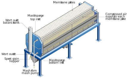
Figure: The main features of a Mash Filter
The mash filter is comprised of a large number of filter plates, combined together to work in parallel.
The plates, made of polypropylene, measure 1.8 m x 2.0 m. In our example there are two types of plate – filter plates and membrane plates (other designs are possible, in which every plate has both elements).
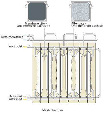
Figure: The filter plates and membrane plates
Each filter chamber will hold a nominal 175 kg of grist. 58 chambers are thus needed for 10 t of grist.
Each filter plate has a polypropylene filter cloth either side. This provides just under 2 x 3 m² of filter surface area. The cloth pore size ranges from 0.5-200 micron.
The membrane plates are fitted each side with a flexible and non-porous rubber membrane made from EPDM (Ethylene Propylene Diene Monomer). Each membrane is connected to an air system, which can either supply air to inflate the membranes (like a rubber bladder), or vent air out to deflate them. Some designs operate the membranes using water rather than air.
The 58 alternating filter plates and membrane plates are held together very tightly by a hydraulic ram, applying 120 bar to ensure no leakage during operation.
As previously seen, the lauter tun and mash tun control their flow by regulating the flow away from the device. This avoids exceeding their DP design limit. The mash filter regulates the flow into it with a mash pump.
We will start wort filtration in flow control. The pump speed modulates to achieve the target flow rate. However, if the inlet pressure gets to its pressure limit, we need to change the filter to pressure control. This reduces the pump speed and flow rate, so as not to exceed the 0.5 bar.
The lauter tun and mash tun are regulated to not exceed their DP design limit of roughly 0.1 bar. The mash filter has a design limit for its inlet pressure of 0.5 bar. Its DP across the grain bed is approximately 0.3 bar.
The wort outlets feed a balance tank which is maintained at a level just above the top wort outlet. This maintains constant hydraulic balance within the mash filter, resulting in the same volume and husk solids within each chamber. The balance tank outlet supplies a variable speed pump, which responds to maintain its level constant.
As we saw earlier, the lauter tun and mash tun sparge by spraying water from above the grain bed and flowing through it. The mash filter has sparge water supplied to its mash pump. The sparge takes the same route as the mash and flows through the grain beds.