
Lesson 4 - Wort Separation Technology
This lesson deals with wort separation technology. The variables of Darcy’s Law are re-visited, to demonstrate how they influence the design of the lauter tun, mash tun, and mash filter. The key design features and control methods of these wort separation devices are identified. Typical operational steps and times are also established for each device.
Automated Control of the Lauter Tun
We will programme the lauter to run with a particular flow profile, in order to achieve the required cycle time.
The rakes will be used to automatically reduce any excessively high occurring DP. The data from the control system allows us to create a trend of the process performance of the lauter tun. The example below is just one of many ways that a lauter tun is controlled. Details vary between the available lauter tun designs, but the main parameters will be similar:
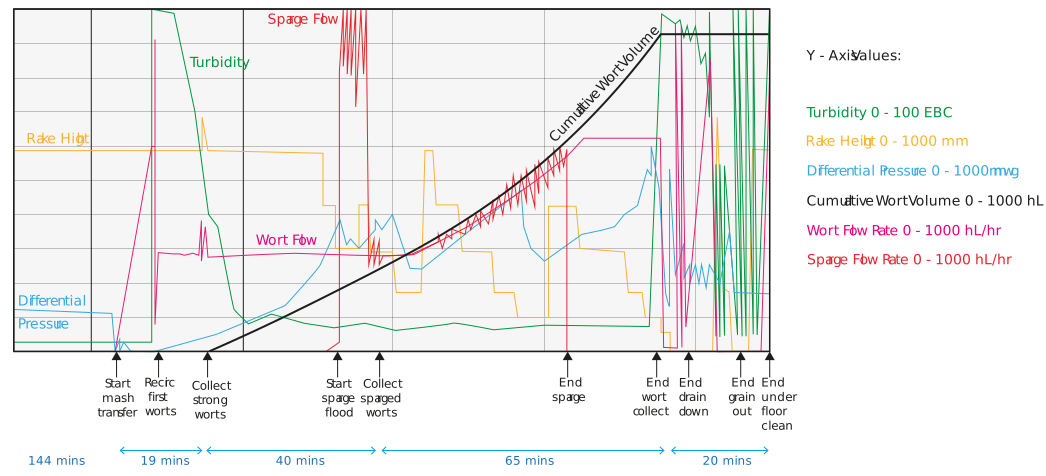
Figure: A trend of lauter tun wort collection
The sensors are continually monitoring DP and turbidity. Not shown here is that some units have an in-line density meter in the outlet pipework. The gravity can be integrated into the control system and it can also provide a measurement of the extract recovered.
In the above example we will have pre-programmed both the flow of wort and sparge to achieve the required cycle time. If DP increases, rather than reduce the wort flow, we will use the rakes to improve grain bed permeability. However, if the DP limit is exceeded, the unit will carry out a deep bed rake. The distance from the bottom of the rakes to the false floor is measured, and then displayed as rake height.
During recirculation of first worts, the rakes are not needed as DP is low. The high turbidity falls to 40 EBC, and we can start strong worts collection. The turbidity continues to fall to < 10 EBC and is maintained at that for the rest of the worts collection. From the trend shown, we can see that during strong worts collection, the DP starts to rise due to the grain bed compacting. To counteract this, we use the rotating rig and lower the rakes into the grain bed. The rake height is set in accordance with the DP value. The higher the DP, the deeper the rakes ‒ but not at the expense of wort turbidity. In practice, our rakes will not be used any lower than 50 mm above the false floor, to avoid any deterioration in wort clarity.
At a pre-set strong worts collection volume, we now apply the sparge. Initially, sparge flow is high, to replace the volume of strong worts collected. This means that the depth of the supernatant wort above the grain bed is now as it was at the start of wort collection. When this has been achieved, we set the sparge flow to match the wort flow. Rakes are used to modulate the DP. As the sparged worts become weaker in gravity and viscosity, we can ramp up the wort flow rate and matching sparge flow rate between 2.5-3 times the strong wort flow.
At the end of sparged wort collection, the rakes are at their lowest position. This helps minimise the residual liquid in the grain bed. After the grain bed drain-down is complete, the rakes are fully raised. The spent grain plough bar is lowered to line up with the bottom of the rakes. The rig is then gradually lowered into the grain bed, and the plough bar pushes the grain forward and outward to the spent grain discharge opening. When the rig reaches its lowest point, all the spent grain has been removed. The under-floor cleaning jets are then operated to remove any residual fine solids or dough. The rakes and plough bar are then returned to their raised rest positions. We are ready for the next mash transfer.