
Lesson 4 - Wort Separation Technology
This lesson deals with wort separation technology. The variables of Darcy’s Law are re-visited, to demonstrate how they influence the design of the lauter tun, mash tun, and mash filter. The key design features and control methods of these wort separation devices are identified. Typical operational steps and times are also established for each device.
Point of reflection – reconvene
Welcome back. So, what were your thoughts?
The surface area A of the lauter tun is 2.5 times greater than the mash tun, so for 10 t of grist, the grain bed loading is 2.5 times lower, and the resultant grain bed depth L is 2.5 times shallower. Higher A and lower L favours lauter tun flow. However, for the lauter tun we will use a six-roller mill, creating a finer grist with a lower husk fraction. Our grain bed permeability K will be lower than for the mash tun, which is detrimental to lauter tun wort flow. Our thinner mash, and higher wort temperature to the lauter tun, produce a lower viscosity wort which favours lauter tun flow. The lauter tun has a water to grist ratio of 3.2 L/kg.
Now let us substitute the numbers from the above table into Darcy’s Law, to predict a relative flow rate between the two:

Table: Using Darcy’s Law to compare the lauter tun to the mash tun
|
|
Relative K |
DP (bar) |
A (m²) |
µ (mPa.s) |
L (m) |
Q (hL/h) |
Q Ratio |
|
Mash Tun |
275 |
0.1 |
20 |
1.85 |
1 |
378 |
1 |
|
Lauter Tun |
87 |
0.1 |
50 |
1.25 |
0.5 |
889.3 |
2.3 |
Compared to the mash tun, the lauter tun strong worts flow is higher for all the Darcy’s Law variables, except for grain bed permeability. This is why the lauter tun is equipped with rakes. The rakes are used to cut open the grain bed and improve (increase) grain bed permeability.
So what does a lauter tun look like, and how does it work?
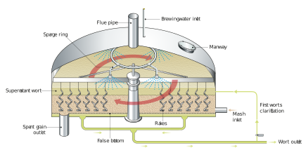
Figure: Simplified main features of the lauter tun
The lauter tun is a circular vessel constructed from copper or stainless steel. It is enclosed, but the flue pipe (vent stack) ensures that it is always open to the atmosphere. This makes sure that we cannot pressurise it during filling or cause a vacuum when we empty it. The shell also has a manway door, so that we can inspect the process in operation, or gain access for repair.
The true floor of the vessel has wort outlets spaced at approximately every 1 - 2 m². Traditionally, the Lauter tun was at an elevated level so that wort would flow by gravity down to an open collection trough called a ‘grant’. Each outlet was terminated at the grant with a flow throttling valve known as a ‘tap’. The operator manually ‘set the taps’ to ensure even outlet flows. It was also critical that this combined flow was not so great that it caused too high a DP, as evidenced by a large drop in the manometer level.
If we have a modern automated lauter tun, the individual outlets combine into increasingly larger diameter pipework, or individually into a small collection chamber. The pipework is designed to ensure even flow from each outlet. So, if we look underneath, we see a maze of pipework.
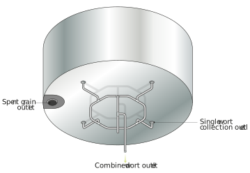
Figure: Wort collection outlet pipework arrangement
The combined flow from the lauter tun is now via one main, and the open grant is eliminated to minimise oxygen exposure. If our flow to the downstream kettle is by gravity, then a throttling valve can be regulated in response to an in-line flow meter. If the flow needs to be pumped to the downstream kettle, then the pump speed can be regulated in response to the flow meter.
So, what can we see inside the lauter tun? The most impressive sight is the rig with arms and attached rakes. Down below, we can see the false slotted floor. Up above, we can see an overhead sparge water ring with its attached spray nozzles.
Lauter Tun Design - The False FloorThe false floor is made up of segmented plates that can be manually lifted for cleaning or inspection. Each segment can either be a solid plate that has milled slots measuring 0.7 mm wide, opening up 10-15% of the total area. Alternatively, each segment can be constructed of wedge wire; in this case, the open area will represent 20-25% of the total area.
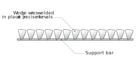
Figure: Cross section of wedge wire floor
The false floor and its slots form a crude sieve to hold back the husk material, but which allows free flow of the wort. The void under the false floor will be between 25-50 mm deep. Historically, regular lifting of the false floor plates was needed to clear the accumulation of fine solids or dough. A modern lauter tun is fitted with under-floor high pressure hot water nozzles to clean the void after each brew. Lifting of the false floor, thankfully, becomes a very infrequent occurrence (typical performed annually to remove grit/sand trapped in the slots).
The false floor has limited strength against vacuum; it is essential that we do not exceed the DP limit of 0.1 bar.
In order to minimise air entrainment, the mash must enter at false floor level. This can be achieved either by side entry, or by pop up valves through the false floor.
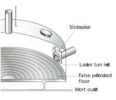
Figure: Low side entry of mash to minimise air entrainment
Lauter Tun Design - The Rig, Rakes and Sparge SystemThe internal rotating rig has a series of arms with attached rakes (knives). As well as rotation at roughly 0.1 rpm, the rig can raise and lower so that the rakes can cut the bed at varying depths. This increases grain bed permeability. There are a variety of rake designs which are used to gently cut and lift the bed, to improve grain bed permeability without increasing wort turbidity (in practice this means that we cannot use the rakes any lower than about 50 mm above the false floor). The rakes on the arm need a minimum spacing of 160 mm to avoid them creating a bulldozer action. This would push the bed instead of cutting it, in turn making our DP worse! We can reduce the spacing between the cuts by off-setting the rakes on the other arms. So with two arms, we can cut the bed every 80 mm. With four arms, we can cut the bed every 40 mm.
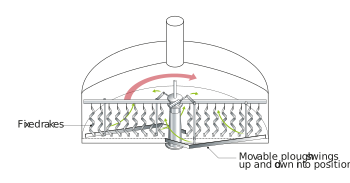
Figure: The rig arms with attached rakes and spent grain removal plough bar
The Sparge System
We will need a sparge system to provide hot water sprays, in order to rinse the spent grain bed of its residual extract. This will be 76-78˚C, the same as the final temperature in the mash conversion vessel. The overhead spray nozzles are distributed so that the hot water spray will fall evenly across the whole of the grain bed surface. (In some designs it is possible to introduce sparge as an integral part of the rakes.)
The sparge must be applied evenly to the whole of the exposed grain bed, to maximise extract recovery.
We can operate with the grain bed remaining flooded throughout wort collection and sparging. In which case, the spray pattern is not as critical as it is for sparging a grain bed with its surface exposed.
Spent Grain RemovalOnce we have completed wort collection, we need to remove the residual spent grain. A circular section of the false floor opens to an outlet connection through the true floor to the spent grain discharge chute.
The spent grain discharge is completed using the rig. It is dependent on the type of rakes we are using.
If the knives are of a flat blade design, they can be turned so that instead of presenting a leading fine cutting edge, they effectively become a plough bar for sweeping the grain.
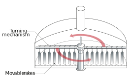
Figure: Turnable rakes
The rig is raised, the rakes are turned to the ‘grain out’ position, and the rig gradually lowers into the spent grain bed. The rotating wall of angled rakes sweeps the grain out to the periphery, where the spent grain opening(s) is/are located.
If our rakes are not of a blade style and are in a fixed position, then we will need an additional shaped plough bar that is lowered to the bottom of the rakes. The rotating plough bar is then gradually lowered into the bed. The grain is swept out to the periphery of the vessel, where it drops down the spent grain valve opening.
Our spent grain can drop directly into a pneumoveyor transfer system to the spent grain storage silo. Graining out this way may take between 30-45 min. However, for our 10 brews per day unit, we will need to grain out in 15 min. In this case, we will have a spent grain hopper directly beneath the lauter tun. This will receive the whole brew of spent grain in 10-15 min. The spent grain hopper can then gradually transfer to a spent grain storage silo while our lauter tun gets on with the next brew.