
Lesson 4 - Effluent Treatment
In this lesson we take a closer look at effluent from a utilities perspective. We will consider different forms of effluent treatment.
Aerobic Effluent Treatment
Aerobic effluent treatment plays an important part in effluent treatment, especially for reuse or where stringent discharge requirements must be met, e.g. if discharging to open water rather than a downstream treatment facility.
Just as for anaerobic effluent treatment, the most rudimentary form of aerobic treatment is a lagoon or pond. This has a large footprint, so activated sludge is instead the preferred method.
Fixed bed reactors are also employed. These function similarly to AFs, and can also take the form of moving beds.
Let us have a closer look at how activated sludge works.
Activated sludge is a flocculated form of aerobic sludge. The process normally has three steps:
-
Accumulation – the sludge is fed with effluent and aerated so that the microorganisms absorb the organic materials
-
Regeneration – these organic materials are oxidised into water and carbon dioxide and new microorganisms are generated
-
Sedimentation – sludge settles out in a quiet zone and the purified effluent can then be removed
The activated sludge reactor is based on the same principle as a CSTR, but there is no need for biogas collection. To improve efficiency, these units can be built into a sequential batch reactor (SBR). Here, either effluent is transferred to different reactors as the process continues or different reactors are operated sequentially through a number of steps. The figure below shows such an operation.
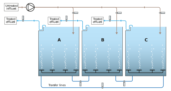
Figure: Aerobic SBR system with full flexibility
Influent can enter compartments A, B, or C and then be transferred to any other compartment. It can be transferred again before finally exiting as treated effluent. This allows for flexibility in cleaning and operation.
A more advanced form of aerobic treatment is the airlift reactor. The water sludge mixture is circulated over internal cylinders by the airlift from the air supplied to the unit. Here we are putting the air to good use. This has a much smaller footprint and higher throughputs. The design also aids the removal of nitrogen. See the figure below.
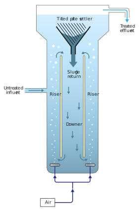
Figure: Aerobic airlift reactor
The table below compares the key parameters for aerobic reactor systems.
Table: Key parameters for aerobic reactor systems
|
Type |
Volumetric Loading (kg COD/m3/d) |
Biomass |
Retention |
Mixing |
|
Lagoon |
0.1 |
Suspended |
|
|
|
Activated sludge |
0.5-2.5 |
Suspended |
External clarifier |
Aeration |
|
Fixed/moving bed |
1-5 |
Attached or suspended |
|
Pump/aeration |
|
Airlift reactor |
5-10 |
Granular |
Internal clarifier |
Aeration/airlift |
Now that we have covered aerobic and anaerobic treatment, can you do a summary comparison of the two treatments? Also consider when you would choose anaerobic and when aerobic. Give yourself 5-10 min to think about this, and then click ’Next’ to continue with this lesson.