
Lesson 4 - Effluent Treatment
In this lesson we take a closer look at effluent from a utilities perspective. We will consider different forms of effluent treatment.
Anaerobic Effluent Treatment
Anaerobic effluent treatment is widely used because of the useful biogas it produces. It is also used because on its own it can in most instances bring the effluent parameters in line with discharge requirements and also does not need much space.
With any effluent system, we need efficiency in order to operate at the lowest cost and where practical take up the least space. What are the main parameters that affect the efficiency of a system? The answer in short is how much biomass you have and how active the biomass is. This is a bit like looking at the size and fitness of your army.
This in turn means that for a system to work well we need good contact between the effluent and the biomass through mixing and turbulence and we need to retain the biomass. Your biomass army needs to get to the effluent, but not be swept away with it!
The traditional anaerobic system is called a lagoon. This is a very large pond with anaerobic biomass at the bottom, with effluent flowing in one side and out the other side. The biomass is not very effective, as there is not much opportunity for contact. Thus, the retention time in the pond must be substantial in order to achieve meaningful results.
To overcome this, the next development was continuous stirred tank reactors (CSTRs). These can be basic stirred vessels or can have a separation unit to reduce carryover, as seen in the figures below. Stirring up the biomass results in greater contact, but at the same time more carryover. The screen on the right allows for any carryover to be recycled back into the unit.
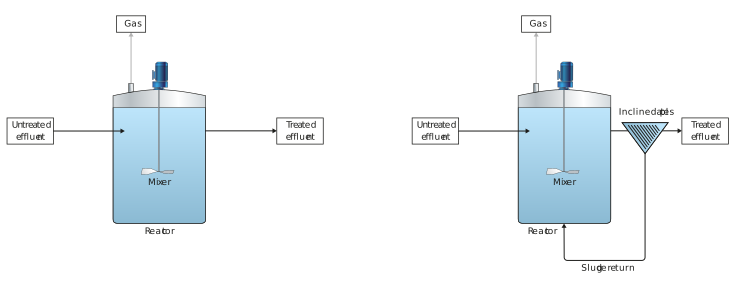
Figure: CSTR without and with separation
CSTRs are not well suited to brewery effluent, which is fairly dilute by wastewater standards. The next development was an anaerobic filter (AF), as shown below.
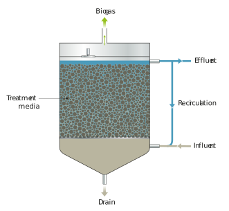
Figure: Anaerobic filter
These filters use carrier material for the biomass to grow on. However, they still presented issues with both clogging and short-circuiting.
Luckily for the brewing industry, the development of the upflow anaerobic sludge blanket (UASB) reactor in the late 1970s provided a solution.
The UASB reactor works with granular sludge of 1-4 mm. This allows for the sludge to have far superior settling abilities. The wastewater flows upward through a dense bed of this sludge, and separation is then done at the top of the reactor between sludge, biogas, and wastewater in a three-phase separator. This is like fitting your army of biomass into little tanks that can infiltrate the effluent but which are far easier to keep bringing back to base. The figure below shows a typical UASB reactor.
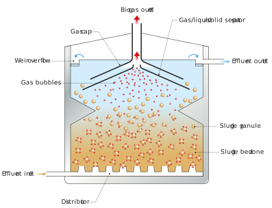
Figure: UASB reactor
In the 1990s, some newer generation reactors made their appearance on the brewery scene. These are very high towers that use slightly different principles to allow for this height (and small diameter).
One of these is the fluidised bed (FB) reactor. This uses a fluidised carrier material that the biomass grows on.
Another version is the expanded granular sludge bed (EGSB), which is essentially a stretched UASB. The internal circulation (IC) reactor is a bit different, as it consists of two UASB reactors on top of each other. The first and lower one is mixed by an internal circuit driven by its own biogas. Most of the biogas is removed in this first stage, which then allows the second stage to be a lot less turbulent, allowing for better separation between biomass and wastewater.
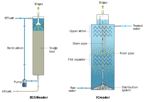
Figure: EGSB reactor and IC reactor
For a great video on the operation of the IC reactor, see the link below. Note: this is for illustrative purposes only, and is not a recommendation or endorsement of the supplier’s product.
There are numerous variations available, and the technology is continuously improving. The original IC design has been upgraded to a unit that can be retrofitted into a standard UASB reactor. This system is called the ICX.
See below video below on the operation of an ICX system. Note: this is for illustrative purposes only, and is not a recommendation or endorsement of the supplier’s product.
The table below shows a summary of these anaerobic reactor parameters.
Table: Design parameters of anaerobic reactors
|
Type |
Volumetric Loading rate (kg COD/m3.d) |
Retention |
Separation |
Mixing |
|
Lagoon |
0.1-1 |
Suspended |
-- |
-- |
|
Continuous stirred tank reactors |
1-5 |
Suspended |
External |
Mechanical/biogas |
|
Anaerobic filter |
5-10 |
Attached |
Filter bed |
|
|
Upflow anaerobic sludge blanket |
5-15 |
Granular |
3-phase separator |
Pump/biogas |
|
Fluidised bed |
10-20 |
Granular on carrier |
3-phase separator |
Pump/biogas |
|
Expanded granular sludge bed |
15-25 |
Granular |
3-phase separator |
Pump/biogas |
|
Internal circulation |
20-30 |
Granular |
Two 3-phase separators |
Pump/biogas/internal circulation |
|
ICX |
20-35 |
Granular |
Two 2-phase separators |
|