Lesson 12 - Heat Transfer End of Unit SAQ
This lesson allows you to test yourself on the material covered in the Heat Transfer unit and determine the level to which you have met the learning outcomes.
Suggested Response - Q4
*** A wort cooler uses chilled water at 5°C to cool wort at 97°C. The chilled water flow rate is 1.05 times the wort flow rate, and it exits the heat exchanger as hot water at 85°C. The specific heat capacity of wort and water are 4,040 J kg-1 K-1 and 4,200 J kg-1 K-1 respectively.
a) What type of heat exchanger and what flow configuration would you recommend for this application? Explain your reasons why.
b) What are the disadvantages of using this type of exchanger for this application, and how can these be overcome?
c) What is the recommended design specification for the wort exit temperature? What is the approach temperature of the heat exchanger?
d) When first installed, the exchanger achieves an outlet temperature of 8°C. What is the reason for this?
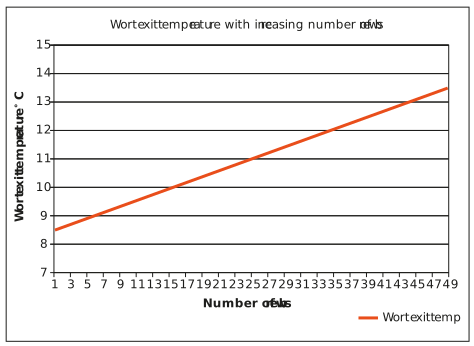
The wort and utilities fluid inlet temperatures and flow rates remain unchanged, yet a graph of the wort exit temperature versus the number of brews collected looks as shown below:
e) What is the reason for the increase in wort exit temperature as more brews are collected?
f) How can the exit temperature be maintained at the design temperature of 9°C?
Response:
a) For this application, a plate heat exchanger would be recommended. This is because:
• The design of a plate heat exchanger forces a high degree of turbulence in both the product and utility fluid. This results in excellent heat transfer rates and thermal efficiencies.
• Hot wort is prone to fouling. The high turbulence of the plate heat exchanger design has an almost ‘self-cleaning’ effect, which reduces the build-up of material on the heat transfer surface. In spite of this, the exchanger must still be regularly cleaned. Plate heat exchangers are easy to clean inline.
• Plate heat exchangers are compact. The required heat transfer of this wort cooler is high. A plate heat exchanger will not take up a large amount of space in the plant.
The wort cooled is not highly temperature sensitive, and so a countercurrent flow configuration is recommended. Countercurrent flow configurations can achieve far greater heat recovery.
b) One of the main disadvantages of plate heat exchangers is that the flow path for the fluids (e.g. the gap between the plates) is very narrow.
• In wort cooling applications, this makes the exchanger particularly prone to blockages, which come from particulate matter present in the wort.
• This is overcome by installing a strainer on the inlet of the exchanger. This prevents material from entering the exchanger and blocking the flow passages. In addition, to reduce the risk of blockages, wort coolers are designed with relatively large plate spacing.
• The narrow flow path of plate heat exchangers also increases the pressure drop through the exchanger. In wort cooling, the system pressure is often already high due to the high head pressure of the fermentation vessel and possibly the long distance between the brewhouse and fermentation vessels. The supply pressure to the wort cooling heat exchanger must be great enough to overcome these pressure requirements, as well as the high pressure drop through the exchanger.
This illustrates another disadvantage of using plate heat exchangers in wort cooling applications: plate heat exchangers are not suited for higher pressure applications. To overcome this issue, often two pumps are installed in the wort cooling line. One to pump the wort through the wort cooling heat exchanger, and another to pump it to and into the fermentation vessel. This solution ensures that the incoming pressure into the heat exchanger is kept within design capability.
c) Both the wort and the chilled water streams are single fluids that are changing temperature, so the following equations can be used:


We are told that:

This is a valid assumption because in plate heat exchangers, the flow rates of the two streams through the exchanger should not differ more than 15% from each other. A high flow differential between the streams through a plate heat exchanger will result in a differential force on the plates that can cause them to bend. If the plates bend, this will place stress on the gaskets, which can lead to failure and leaks. Bending may also damage the plates.
Also:

So,

Based on the principle of the conservation of energy, and assuming that there is no heat loss to the environment, the heat transferred from the wort is equal to the heat gained by the chilled water, so:

Substituting the above into this equation, it can be simplified to:


And so,


In a countercurrent heat exchanger, the approach temperature is the difference between the incoming utility and the outgoing product stream, which is as follows:

Plate heat exchangers can achieve much closer approach temperatures with less heat transfer surface area than other exchanger types. This is another reason why a plate heat exchanger is well-suited to this application.
d) In heat exchanger design, the overall heat transfer coefficient includes an allowance for fouling. The fouling factor lowers the overall heat transfer coefficient.
In determining the required heat transfer area of a heat exchanger, the equation q = UA∆TLM is used. If U is lowered, then A must be increased to ensure that the required heat transfer rate is still met. A heat exchanger area is calculated for the worst case U value that the exchanger will be operated at, e.g. for when it has incurred the highest degree of fouling.
When the heat exchanger is first operated, there is no fouling, and so the actual overall heat transfer coefficient is greater than what was used in the design. Once installed, the heat transfer area will not change, so according to the equation q = UA∆TLM, if U is better than design, then q will be greater than design.
This means that the heat transfer rate in this equation, q = mCp (Tin − Tout), will also be greater than design. The mass flow rate and inlet temperature do not change, so the increase in heat transfer rate translates into a decrease in the exit temperature of the exchanger. This is why the exchanger’s outlet temperature is colder than the design specification when it is first operated.
e) In this graph, the wort exit temperature of the exchanger increases as the number of brews collected through the exchanger increases. This is because over time, fouling builds up on the heat transfer surface of the exchanger. This decreases the overall heat transfer coefficient of the exchanger, and in turn the heat transfer rate. As all other parameters remain constant, when the heat transfer rate drops, the wort exit temperature starts to increase.
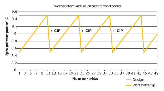
f) The wort exit temperature can be kept below the design specification of 9.5°C by routinely cleaning the heat transfer surface. Looking at the graph, it is clear that the temperature goes out of spec after eleven brews have been collected. Therefore, this heat exchanger should ideally be cleaned after every eleven brews.
For optimal cleaning, it is recommended that the CIP be run with hot caustic solution, in the reverse direction to product flow. If this is done, the wort exit temperature graph would look more like the one below:
Post-cleaning, it is important to check whether the exchanger performance returns to the original design specifications. If this is not the case, then the following may occur over time:
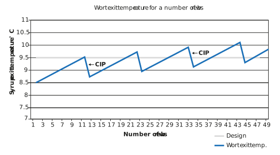
Here, even though the exchanger is being cleaned every eleven brews, the performance is not returning to original design capability. And so, over time, even with cleaning, the exchanger will not meet its performance specification. This indicates that the heat transfer surface is not being effectively cleaned. Adjustments can be made to the CIP parameters to improve the effectiveness of the CIP. If the situation persists, it may be necessary to open up the exchanger and deep clean it. However, this will not be part of normal operating practice, and will need to be scheduled with both production and maintenance planning. Suitably qualified personnel must carry out this work.
While regular CIP will ensure that the exit temperature remains below 9.5°C, the exchanger is still not achieving the target temperature on every brew. This is because when the exchanger is clean, it is exceeding its performance. This can be resolved by using the control system around the exchanger to ‘worsen’ the exchanger performance so that it consistently achieves a wort outlet temperature of 9.5°C on every brew.
In the following equation:
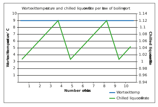
only the mass flow rate of the utility fluid can be adjusted. When the exchanger is clean, the mass flow rate of the chilled water is reduced. This increases the exchanger exit temperature, which in turn decreases the temperature driving force across the exchanger. As the exchanger starts to foul and U starts to reduce, to ensure that q does not drop, the utility fluids flow rate is increased. As shown in the trend below, by varying the chilled water flow rate, we can achieve a wort exit temperature of 9.5°C on every brew.