
Lesson 12 - Heat Transfer End of Unit SAQ
This lesson allows you to test yourself on the material covered in the Heat Transfer unit and determine the level to which you have met the learning outcomes.
Suggested Response - Q3
*** 1,000 hL of wort at a temperature of 79°C is collected to the wort kettle. Wort is heated and boiled by pumping through an external shell and tube heat exchanger with a countercurrent flow configuration.
• The specific heat capacity and density of wort are 4,000 J kg-1 K-1 and 1080 kg/m3 respectively. The heat of vaporisation of wort is 2,256 kJ kg-1.
• The wort boiling temperature is 100°C.
• Steam is supplied to the heat exchanger at a temperature of 140°C. The latent heat of condensation of steam at 140°C is 2,144 KJ kg-1.
• The exchanger has 150 tubes of 32.5 mm diameter and 2.5 m long, with an overall heat transfer coefficient of 2,100 Wm-2 K-1.
a) Define the overall heat transfer coefficient as it applies to this example.
b) List three design features of shell and tube heat exchangers that improve their overall heat transfer coefficient. List these in order of biggest to smallest influence.
c) What would be the downside of the design features suggested in b) for this application?
d) What is the evaporation rate (%) after one hour of boiling?
Response:
a) The overall heat transfer coefficient, U, is a measure of the ability to transfer heat through a surface or layers of material. It considers the resistance to heat transfer via all forms of heat transfer, including conduction, convection, and radiation. Each term in the equation for U represents a resistance to heat transfer.
In this example, U would be calculated from:
-
The film heat transfer coefficient, h, for the inside and outside of the material. In shell and tube exchangers, the heat transfer coefficient can be calculated using either the inside or outside tube diameter. Depending on which one is selected, the inside or outside film transfer coefficient is normalised for the respective diameter.
-
The term k/x which characterises the heat transfer through the heat exchanger tube walls, with the thickness of x and a thermal conductivity of k.
-
r, which characterises the expected worst case resistance that is expected to build up on the heat transfer surface from fouling just prior to cleaning.
b) The film coefficients of the product and utility fluid have the largest influence on the overall heat transfer coefficient.
-
A way in which film coefficients can be improved, is by increasing the product fluid velocities. In the design of shell and tube exchangers, this can be achieved by:
-
having more, but narrower, tubes; and
-
installing turbulators in the tubes to enhance the turbulence of the tube side fluid.
-
-
Furthermore, film coefficients are improved by increasing the utility fluid velocities. In the design of shell and tube heat exchangers, this is achieved by:
-
Adding vertical or helical baffles in the shell to enhance the turbulence of the shell side fluid – this has a greater influence when the utility fluid is changing temperature, and far less of an influence when it is changing phase.
-
Although they have a far smaller influence, there are also other ways in which overall heat transfer coefficients can be improved. These include:
-
Minimising the thickness of the heat transfer surface – this would be achieved in a shell and tube heat exchanger by making the tube walls thinner.
-
Selecting a good conducting material for the heat transfer surface –copper, for example, is an excellent conductor of heat.
c) The features in b) can also negatively affect the performance of the heat exchanger. For wort boiling with an external shell and tube heat exchangers, these negative impacts are as follows:
-
Increasing product fluid velocity will result in an increase in pressure drop through the heat exchanger.
-
In this example, having narrower tubes will improve the overall heat transfer coefficient, but it will also increase the pressure drop. To overcome a high pressure drop across the external heat exchanger, the supply pressure of the wort must be increased. This will require a larger recirculation pump, which will increase the capital and operating costs of the heat exchanger system. This cost must be balanced against the improvement in heat transfer performance from the narrower tubes.
-
Some wort kettles are designed to circulate by using the thermosyphon effect rather than using a pump. To be effective thermosyphon boilers require a very low pressure drop across the exchanger. If the pressure drop is too high, the wort will not circulate, and boiling will be ineffective. In this application, the tube diameter will be larger than the optimum size so as to minimise pressure drop. This however, lowers the overall heat transfer coefficient. This is typical in heat exchanger designs where one design parameter has to be balanced against another.
In this example, because the utility fluid is changing state including features that improve the utility fluid’s velocity would increase the cost of the exchanger but have very little impact on its performance; these features should therefore not be considered.
-
Boiling wort is prone to fouling and blockages, so in this example, any features that increase the risk of fouling or reduce the ability to clean the exchanger properly should be closely considered. While turbulators and smaller tubes will improve the fluid velocity, they will also cause more rapid blocking of the exchanger tubes, which will negatively impact the overall heat transfer coefficient more than it will benefit it.
-
Reducing the thickness of the heat transfer surface increases the risk of cracking or pinhole leaks. This in turn increases the risk of cross-contamination between product and utility streams. In shell and tube exchangers, there is a particularly high risk at the point where the tubes are attached to the tubesheet.
d) Let’s begin by calculating the area of the heat exchanger:
SA(tube) = πdL = π × 0.0326 × 2.5 = 0.26 m2
SA(exchanger) = SA(tube) × number of tubes = 0.26 × 150 = 38.4 m2
Next, let’s draw the temperature profile through the exchanger and calculate the ∆TLM:
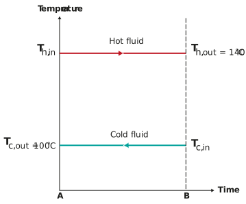
Before jumping into the calculation for ∆TLM, let’s look closely at the temperature profile. ∆TLM represents the average temperature difference between the product and utility fluid across a heat exchanger. So, when you have two constant temperature processes such as condensing steam and boiling wort, the temperature difference across the exchanger is constant and there is thus no need to calculate ∆TLM.
Because the temperature difference across the exchanger is constant, the overall heat transfer rate can be calculated using the following equation:


The total energy added after one hour of boiling is:

Now, using the equation for a single fluid changing state (boiling), calculate the amount of wort to be evaporated by this heat:


Calculate the total mass of wort in the vessel:

Calculate the % of the total mass that was evaporated:

Typical evaporation rates in wort kettles range from 1-5%, depending on the boiling technology used and the process requirements.