
Lesson 9 - Heat Exchangers SAQ
This lesson allows you to test yourself on the material covered in the Heat Exchangers lesson and determine the level to which you have met the learning outcomes.
Suggested Response - Q7
** A brewery has an existing plate heat exchanger that uses steam to generate hot water for brewhouse and CIP operations.
• Incoming water temperature = 25°C
• The specific heat capacity and density of water is 4,200 J kg-1 °C-1 and 1,000 kg m-3 respectively.
• Steam is supplied to the exchanger at a temperature of 140°C. The heat of evaporation of steam at 140°C is 2,144 KJ kg-1.
The design documentation for the exchanger is not available, but the following measurements were taken:
• Plate width = 0.2 m
• Plate height = 0.5 m
• Number of plates = 35
• Flow configuration is counter-current
a) Assuming an overall heat transfer coefficient of 4,000 Wm-2 K-1. What volume of hot water at 85°C can the exchanger generate in one hour?
b) What mass flowrate (kg s-1) of steam is required to deliver this performance?
c) You observe that the exchanger is achieving the water flowrate calculated in a) and an outlet temperature of 85°C but to achieve these outputs the control valve on the steam supply line is open more than normal and the steam temperature to the exchanger is now 145°C. Use the various heat transfer equations to explain what is happening. What can be done to reduce the steam temperature while still achieving the performance specification of the heat exchanger?
Response:
a) Let’s work through the problem step by step.
i. The first step is to calculate the heat transfer area of the existing heat exchanger.


ii. Next, draw the temperature profile through the exchanger.
In this example, the utility fluid is changing phase rather than temperature. This can be seen in the temperature profile drawn below.
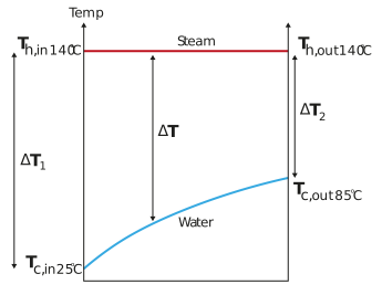
iii. Once you have a clear picture of the temperature profile, it is then possible to calculate ∆TLM.
We will start by calculating the temperature differences at the inlet ∆T1 and outlet ∆T2 of the exchanger.


And


Now you can use the values calculated for ∆T1 and ∆T2 to determine ∆TLM.


This answer can be verified by simply calculating the mean of ∆T2 and ∆T1. This is 85°C which is quite close to the calculated value for ∆TLM of 81.35°C.
iv. Next, using the formula for overall heat transfer rate across an exchanger, calculate the heat transfer rate.


Now using the formula for single fluid that is changing temperature, calculate the mass flowrate of the hot water stream.


v. Finally, calculate the volumetric flowrate per hour.


The heat exchanger can generate 16.3 m3 hr-1 of 85°C water.
b) Using the equation for a single fluid that is changing phase, calculate the required mass flow rate of the steam.


c) Let’s start by looking at the equation for heat transfer from the water
Because m, Cp and ∆T remain unchanged, we can say that q is not changing across the exchanger. Furthermore,
With the increase in steam temperature lets see what happens to ∆TLM

And


Now you can use the values calculated for ∆T1 and ∆T2 to determine ∆TLM.

This is greater than the original design of 81.35°C. The area of the exchanger is fixed and q, the heat transfer rate is not changing Therefore, if ∆TLM is greater than design, U must be lower than originally specified.
The general equation for overall heat transfer coefficient is

The film transfer coefficients (h1 and h2) are not changing as the heat transfer properties and flowrate of the water and steam are not changing.
The thickness of the plates (x) and their conductivity (k) are not changing as the exchanger plates are not changing.
Therefore, the only parameter that remains to be lower than design specification is the fouling resistance (r). Typical values for overall heat transfer coefficient for plate heat exchanger with cold fluid water and the hot fluid steam are between 3,500 – 4,500 Wm-2 K-1 so the original value of 4,000 Wm-2 K-1 seems reasonable for a clean exchanger.
It is most likely that the exchanger is requiring more steam than designed to achieve its performance specification because there is scale build up on the water (tube) side of the heat exchanger.
If possible, a CIP should be run through the heat exchanger. Scale is best removed by cold acid cleaning solutions. If this is not possible the exchanger must be opened up and the plates cleaned manually.