
Lesson 6 - Principles of Fluid Mechanics 3
This lesson considers the factors which contribute to pressure loss when fluid follows through a pipe or duct system. It will examine in detail, the factors which contribute to frictional pressure losses and also losses due to the presence of fittings in the pipeline.
Combining Frictional and Fitting Pressure Losses
Combining frictional and fitting pressure losses is comparatively straightforward, and we deal with it in much the same way as we do with combined serial fitting losses – we sum the various individual pressure losses. However, it is often necessary, in practice, to be able to determine not only the overall pressure drop along the length of a main or duct but to potentially determine the pressure of the fluid at a specific point along the length. This is often required to ensure that excessively low pressures do not exist in the line at a particular point. This could result in dissolved gases coming out of solution or hot liquid releasing vapours (more on these topics in a later lesson).
The following example illustrates how to determine both overall line pressure drop as well as investigating a particular pressure condition within the line.
A high-gravity beer main is shown below (not to scale) with detail as given. The gauge pressure at inlet to the main (A), is 200 kPa and the flow rate is 400 hL/hr.
What is the overall pressure drop between the inlet (A) and outlet (C)?
Consideration is being given to introduce a dilution stream at point B. In order to ensure that the supply pressure of dilution water is sufficiently high to overcome the beer main pressure, determine what the pressure would be at B.
The pipeline is 75 mm internal diameter with an absolute roughness of 0.05 mm. The length of the bends can be ignored. Beer density is 1,010 kg/m³ and dynamic viscosity is 3 cP.
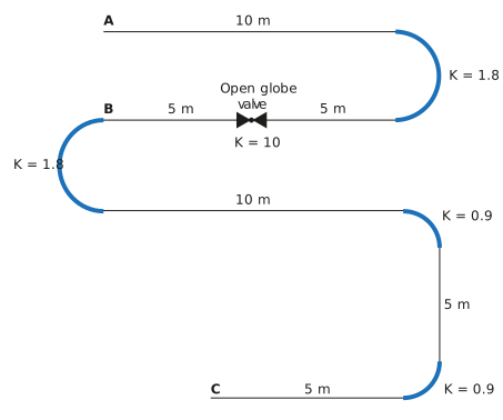
As we will require the average flow velocity to determine velocity heads for the fitting losses, and the flow Reynolds number for pipe friction factor, let us work these out as we have done before:

So, rearranging for u:

Hence the pipe Re is:

Let us deal with the friction pressure loss first for the entire pipe run. The Darcy-Weisbach equation is:

The complete pipe length L is (10 + 5 + 5 + 10 + 5 + 5) = 40 m.
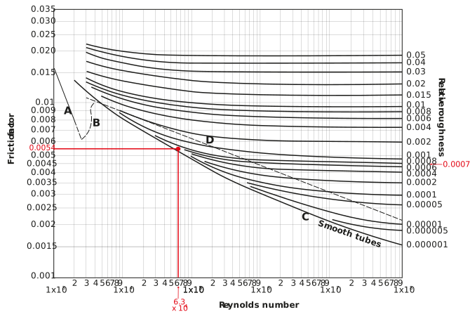
In order to determine the friction factor from a Moody diagram, we need the Re (which we have just calculated) and the relative roughness ε, which is given by:

From the Moody diagram, the friction factor φ is 0.0054.
Therefore, the total friction pressure drop is given by:


Let us also express this as a friction pressure drop per metre run of pipe, (72.7/40) = 1.82 kPa/m.
The total fitting loss will be the sum of the loss coefficients for the four bends and the open globe valve:


Therefore, the total pipeline pressure drop is given (72.7 + 48.6) = 121.3 kPa.
In order to determine the pressure at B, we need to determine the pressure drop between A and B, which consists of a pipe run of (10 + 5 + 5) = 20 m and a 180° bend and an open globe valve.
We previously determined that the friction loss per metre of pipe run is 1.82 kPa/m, hence the friction pressure drop of the 20 m pipe run is 20 x 1.82 = 36.4 kPa.
The pressure loss due to the fittings is given by:


Hence ∆PA-B = 73.6 kPa
It is worth noting that the fitting and friction pressure losses are very similar, which may be unexpected and is largely due to the high loss coefficient of the open globe valve. This is an example of taking note of high loss coefficient fittings, and in practice, questioning whether they cannot be replaced by lower loss coefficient alternatives, or moved to a different part of the pipeline.
As PA = 200 kPa. We can determine PB:


We have now dealt with pressure drops in the pipe/duct system, and the different causes of pressure drop. We will now finish this lesson with a few thoughts on how we choose flow velocities and allowable pressure drops.