
Lesson 6 - Principles of Fluid Mechanics 3
This lesson considers the factors which contribute to pressure loss when fluid follows through a pipe or duct system. It will examine in detail, the factors which contribute to frictional pressure losses and also losses due to the presence of fittings in the pipeline.
Fitting Pressure Loss – Worked Example
Let us look at a worked example where we calculate a fitting pressure loss.
Example:
A fitting with a loss coefficient of 0.9 is present within a 125 mm internal diameter wort main. If the wort flow rate is 1,000 hL/hr, what will be the pressure loss across the fitting? Wort density is 1,050 kg/m³.
Stating the fitting pressure loss expression:

Hence, we need to determine the average flow velocity u from continuity considerations, as we have been given all other values to solve this equation.

So, rearranging for u:

And substituting into the fitting pressure loss expression:


Pipeline systems with multiple fittings
Practical pipeline systems are generally not restricted to a single fitting in the line, but rather multiple fittings. So, what do we do to determine the pressure loss through a number of fittings which are in a series within a pipeline? Serial fittings in a pipeline are probably the most common arrangement, for example, of moving fluid from tank A, through a pipeline to tank B. Well, we simply determine the pressure drop through each fitting and then sum them up.
Pipelines, with parallel arms and fittings in each arm, are a bit more complicated and we will not consider these further. If you are presented with these in practice, it is time to call a friendly engineer!
In a pipeline with a number of fittings in a series, we simply determine the pressure drop through each fitting and then sum the pressure drops up.
Let us look at a worked example to clarify this.
Example:
A bulk caustic tank is connected to a supply main where the mean flow velocity is constant throughout the main at 1.9 m/s. The main consists of an exit from the bulk tank: a half open gate valve and six threaded 90° elbows.
What would be the pressure drop along the length of the main due to fitting losses only? The caustic density is 1,200 kg/m³.
The loss coefficients are as follows: k=0.5, exit from the tank; k=0.9, 90° elbow; and k=5.6, 50% open gate valve.
The first thing to do is sketch the tank/main set-up:
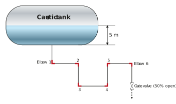
The total fitting pressure loss will be given by:

Where each term is given by:

Note that in this case, the average flow velocity is the same in all cases (we were told this in the question), so we can group all the u² ρ/2 terms thus:


Now that we have covered how to determine the pressure loss due to fittings, and previously covered pressure loss due to friction, we can put both elements together to examine pressure loss along a pipeline due to the losses incurred from fittings and friction. Let us look at that next.