
Lesson 4 - Principles of Fluid Mechanics 2
This lesson will extend our knowledge of fluid mechanics by considering two important laws: the conservation of both mass and energy. We will also examine the various flow regimes which are present within a pipe or duct carrying moving fluids.
Bernoulli’s Equation – Brewery Application
Worked example:
The pressure in the headspace of a cylindroconical fermenter (the gas space above the fermenting beer), requires measurement with a pressure gauge.
Two locations are possible (A and B in the figure below), with location A being in the sidewall of the fermenter, just above the liquid level, and B in the bung line (the CO2 exit pipe).
If the CO2 flow rate is 180 kg/h, would you expect there to be any difference in the pressure reading between the two locations? If so, estimate the relative difference.
The diameter of the fermenter is 5 m, and that of the bung line is 50 mm. The vertical interval between locations A and B is 3 m. The density of the CO2 being evolved from the fermentation is 1.9 kg/m3.
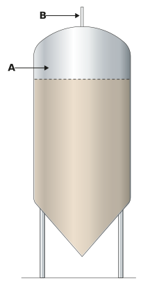
This might seem like a slightly unreal situation, but actually, it is an important everyday problem in every such fermenter. Let us think of this as a large diameter vertical pipe (the fermenter itself) with a contraction of diameter down to the bung line, through which the CO2 flows, as follows:
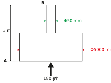
From Bernoulli’s equation, we can clearly see several things are different from location A and B:
-
There is a difference in gravitational potential energy, due to the 3 m head between locations A and B.
-
The diameter reduces significantly in location B compared to A. By considering the continuity of mass, we would expect the velocity of the CO2 to be considerably higher at B than A. Consequently, we would expect the kinetic energy to also be higher at B than A.
-
As the sum of pressure, gravitational potential energy, and kinetic energy sum to a constant (Bernoulli’s equation), we would expect these differences, as described, to result in different pressure values at A and B.
Let us formulate Bernoulli’s equation for locations A and B:

We are assuming that there is no loss or gain of any other form of energy and that the CO₂ density is constant.
Rearranging this equation for (PA - PB):

We can determine uA and uB by considering the continuity equation:

The areas AA and AB are respectively 19.63 and 0.002 m2. (The fermenter and the bung line are circular cross-sections – satisfy yourself that these areas are correct).
uA is determined by rearranging the continuity equation as follows:

In a similar way, uB is determined as:

We should note here the massive increase in the gas velocity between that in the fermenter and in the bung line (nearly a 10,000 times increase).
Considering our equation for the difference in the pressures at A and B:


The pressure reading at location A would be roughly 219 Pa higher than at B. This might not sound a lot, but in practice, it is common for headspace pressures to be controlled to less than 5,000 Pa g. Therefore, it could be significant that there is a difference of 219 Pa due to the location of the pressure gauge (a 4.4% difference).
So far, when we have studied the energy aspects of dynamic fluids via Bernoulli’s equation, we have considered the fluid to move with an average velocity. However, in reality, fluids move within pipes, for instance, with differing velocities across the pipe section, which can create very different behaviour. We need to be aware of this.
Let us now look in some detail at the differing flow behaviour of dynamic fluids.