
Lesson 4 - Principles of Fluid Mechanics 2
This lesson will extend our knowledge of fluid mechanics by considering two important laws: the conservation of both mass and energy. We will also examine the various flow regimes which are present within a pipe or duct carrying moving fluids.
Conservation of Mass
The conservation of mass, at least as a concept, shouldn’t be new to you. Think of it as the old phrase, ‘you get nothing, for nothing’. If you added one kilogram of water to one kilogram of beer, what would you expect to get? That’s right, two kilograms of disappointingly diluted beer! As much as we might wish to get more mass out of such a dilution, we are unable to due to the conservation of mass.
Mass as a quantity is conserved at all times. It can be converted into different forms, through reactions etc., but the sum of the mass of reactants will equal the sum of the mass of products (assuming all reactants are converted and no losses).
The conservation of mass applies to both batch and continuous processes. If you need a reminder of the difference between batch and continuous processes, think about the difference between a bath and a shower.
-
Filling a bath is a batch process – If we put in batches of hot and cold water, stir them together to get the temperature just right, the batch (bath) is ready.
-
A shower is a continuous process – two streams of hot and cold water being mixed together on the way to the shower head, will hopefully create the right temperature for the shower.
As we are considering fluid dynamics, let us think in more detail about the conservation of mass in a continuous process by looking at fluid flowing within a pipe of differing diameters in the figure below.
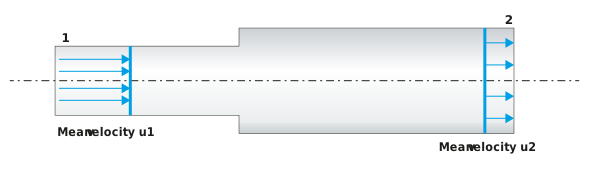
Figure: Fluid flowing through a pipe of differing diameters
At section 1, which is where the fluid enters the pipe, the fluid has a mean velocity of u1. By mean velocity, we mean that the velocity is the same across the entire section of the pipe. At the pipe outlet, section 2, the pipe diameter has increased so that the mean velocity has now reduced to u2.
When the flow is steady, i.e. it does not change flow rate over time, we call it the steady-state. From our earlier discussion, we know that the mass of fluid entering the pipe at section 1, over a time (t) will be equal to the mass of fluid leaving the pipe at section 2 over the same time (t). Instead of thinking of a mass of fluid entering or leaving the pipe over a time (t), we can instead think of the mass flow rate of fluid G (kg/s). Continuity of mass would suggest the following:

Now how can we determine an expression for the mass flow rate G? Well, we can relate that to the volumetric flow rate Q (m3/s) and the fluid density ρ (kg/m3), by being aware that density ρ (kg/m3) is the ratio of the mass (m) of a fluid to its volume (v):

As we are dealing with a flowing fluid in a pipe instead of relating mass and volume, via density, we can relate mass and volumetric flow rates, via density, as:

Rearranging the equation for mass flow rate G gives us:

The volumetric flow rate Q (m3/s) can be determined by thinking of the fluid flowing within the pipe as a solid cylinder travelling down the pipe at the mean velocity u. In that case, the volumetric rate would be given by the mean velocity u (how fast the solid cylinder is moving), multiplied by the cross-sectional area A:

Substituting this relationship into our relationship for mass flow rate gives us:


As mass is conserved (continuity of mass), we can apply this equation to both the entry and the exit of our pipe:

This equation is an important mathematical representation of the continuity of mass and is one example of a continuity equation:
Let us now apply the continuity equation in a worked example.
Example:
A wort main feeds wort into a fermenter. The steady-state flow rate is 800 hL/h, and the internal diameter (ID) of the main is 150 mm. What is the average flow velocity in the 150 mm main?
If we wished to avoid foaming of the wort when it enters the empty fermenter, by reducing the mean flow velocity to below 1 m/s, at the inlet to the fermenter, what would be the required increase in the main diameter at that point?
Let us sketch a diagram so that we understand what is being asked.
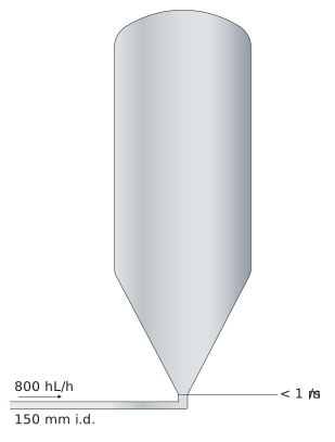
The average flow velocity in the 150 mm main is given by consideration of the following equation:
Rearranging for the average flow velocity u gives:

Firstly, we need to convert the volumetric flow rate Q of 800 hL/h into units of m3/s. Note that 1 hL equals 0.1 m3, and 1 h equals 3,600 s.

We then need to determine the cross-sectional area of a 150 mm main:

Therefore, the average wort velocity is given by:

As we wish to reduce the average flow velocity at the entry to the fermenter to less than 1 m/s, we will need to increase the main diameter accordingly. So, rearranging our volumetric flow rate equation for area gives:

The diameter of a circle of area 0.022 m2 is given by:

Therefore, rearranging for d:
