
Lesson 2 - Principles of Process Control
This lesson explores exactly what process control is and explains why it is important. It examines the various levels within process control systems and identifies the associated equipment. It also takes a detailed look at the various automation communication and control elements.
Control Symbols
Instrumentation and controls are represented by a bubble. Similar to a comic book, the bubbles give us the storyline. The shape of the bubble and the nature of the lines inside it, both tell a story.
Let us start with the shape of the bubble. It can take the following forms:
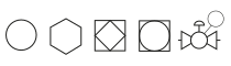
Figure: Bubble shapes and locations
-
A circular bubble shows discrete instruments. It can also be used to tag a valve, as shown in the figure above.
-
A hexagonal shape represents a computer.
-
A square represents a shared display or control and typically represents a controller or PLC.
-
The diamond shape indicates a safety system.
The line inside the bubble also tells a story of its own:
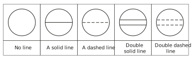
Figure: Lines in a bubble
If there is no line, this means that the device is physically located in the field. A single line means that the display is on a main panel or SCADA. A double line means that the display is on a local panel. Dashed lines mean that the display is hidden from the operator.
The following figure shows how these are combined:
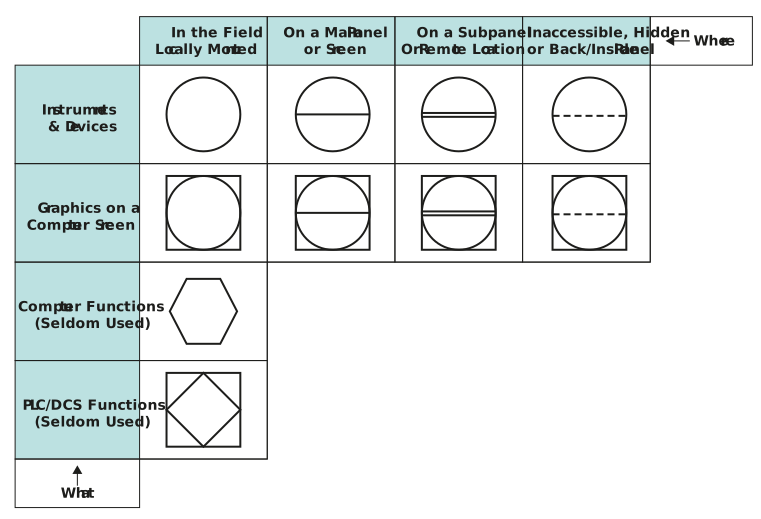
Figure: Tag shapes
We can now explore what is inside the bubble:
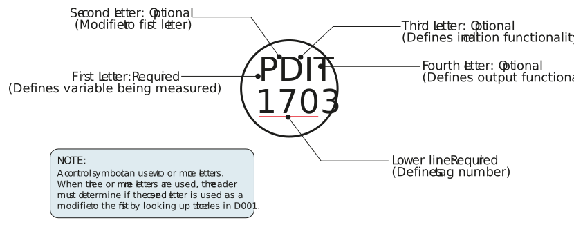
Figure: Tag identification
We can now tackle the final piece of the puzzle – what do all the letters mean?
Once again, the answer varies greatly between different standards, however the basics are, thankfully, the same.
The first letter usually defines the variable that is being measured, e.g. pressure (P), temperature (T), or flow (F).
The next letter (if there is one, as sometimes it is not needed) is a modifier to the first letter. An example of this would be differential pressure (PD).
The following letters define the instrument’s functionality, for example transmitter (T), recorder (R), indicator (I), switch (S), or controller (C). Therefore, a pressure transmitter would be PT, but if it is a pressure transmitter and indicator, it would be PTI.
The last letter is sometimes a modifier of the preceding letters. This could be something like high (H) or low (L). So, a level switch high would be LSH.
To complicate matters (or, perhaps, to simplify them), we can then split the instrument functions into more than one bubble.
The figure below gives some examples of how this works:
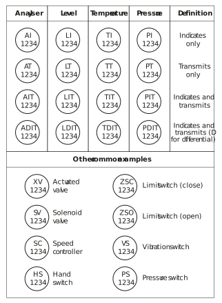
Figure: Common instrument tags
The following table lists the most common letters and explains what they stand for:
Table: Tag letters
|
Letter |
Measured Variable |
Modifier |
Readout |
Device Function |
Modifier |
|
A |
Analysis |
|
Alarm |
|
|
|
C |
User’s choice |
|
|
Control |
|
|
D |
User’s choice |
Differential |
|
|
|
|
E |
Voltage |
|
Sensor (primary element) |
|
|
|
F |
Flowrate |
Ration (fraction) |
|
|
|
|
H |
Hand (manual) |
|
|
|
High |
|
I |
Electrical current |
|
Indication |
|
|
|
L |
Level |
|
Light |
|
Low |
|
P |
Pressure, vacuum |
|
Point, test connection |
|
|
|
Q |
Quantity |
Integrate, totaliser |
|
|
|
|
S |
Speed, frequency |
Safety |
|
Switch |
|
|
T |
Temperature |
|
|
Transmit |
|
|
V |
Vibration, mechanical analysis |
|
|
Valve, damper, louvre |
|
|
W |
Weight, force |
|
Well |
|
|
|
X |
Unclassified |
X-axis |
Unclassified |
Unclassified |
Unclassified |
|
Y |
Event, state, or presence |
Y-axis |
|
Relay, compute, convert |
|
|
Z |
Position, dimension |
Z-axis |
|
Driver, actuator |
|