
Lesson 2 - Principles of Process Control
This lesson explores exactly what process control is and explains why it is important. It examines the various levels within process control systems and identifies the associated equipment. It also takes a detailed look at the various automation communication and control elements.
P&ID Symbology
The standard way to represent a process and the control is called a piping and instrumentation diagram (P&ID).
A P&ID shows the piping, equipment, instrumentation, and control devices. Before we explain more about process controls, instrumentation, and control loops, we should first try to understand how to read a P&ID. In the same way that maps help us to navigate the world, P&IDs help us to navigate the process. A number of organisations have published standards for P&IDs. These standards include the following: ISA (Instrument Society of America), DIN (Deutsches Institut für Normung), PIP (Process Industry Practices), ISO (International Standards Organization), and BS (British Standard). While called standards, they do not all agree with one another.
To complicate matters further, many companies have developed their own versions of this over time. Fortunately, they are all fairly similar; if you understand one system, you should be able to quite easily understand another. The figure below shows part of a typical P&ID diagram:
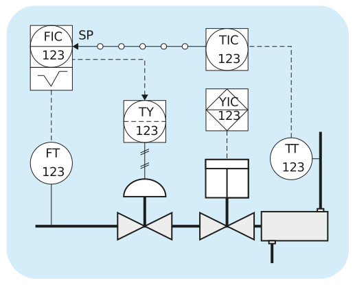
Figure: Part of a P&ID
Let us now explore the components from within this drawing. For the purposes of this lesson, we will loosely stick to the ISA standards.