
Lesson 2 - Principles of Process Control
This lesson explores exactly what process control is and explains why it is important. It examines the various levels within process control systems and identifies the associated equipment. It also takes a detailed look at the various automation communication and control elements.
Control Elements
In order to be able to control a process, we must use equipment of one form or another.
We can carry out control using simple on/off control, such as by opening and closing routes, or starting or stopping equipment. Where parameters need to be controlled, we can control equipment with variable outputs to achieve the desired result.
We will briefly look at the mechanisms of these control elements:
Solenoid valves
Solenoid valves are mainly used to control instrument air to the valves, but the same principle is used to control valves for water, steam, and other fluids. Solenoid valves work with an electromagnet and a plunger. When the electromagnet is energised, the plunger is pulled up, allowing air to pass through. When the magnet is de-energised, a spring pushes the plunger back down and closes the air flow. The figure below shows how this works:
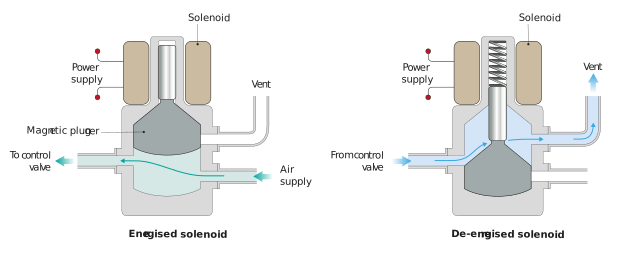
Figure: Operation of a solenoid
The operation can also work the other way around, where the airflow can be closed by energising the plunger. The modes of operation are referred to as normally closed (NC) and normally open (NO).
Pneumatic valves
Pneumatic valves convert the pneumatic energy from the air supply into mechanical energy. There are three types of operation: air to open (ATO), air to close (ATC) and ATO/ATC, which essentially means the valve will stay in position if a failure occurs. The figure below shows these three types of operation:
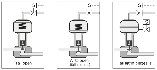
Figure: Fail safe positions of valves
The first valve in the figure above uses air to close the valve. Thus, if the air falls away, the valve will open. The second valve uses air to open the valve. If the air falls away, the valve will close. Whilst in the third valve, the air is controlled and the valve will thus retain its position, even if the air falls away. This is important to know in the event you either have a failure in the air system or a power failure. How the valve reacts in a failure condition directly affects the safety of you and your equipment.
Pneumatic control valves
Pneumatic control valves are extensively used to control flowrates. We will not explore the workings of the valve itself but will instead focus on the actuation (mechanism of opening, closing, or changing position) of the valve.
Pneumatic valves fitted with an electro-pneumatic converter (I/P converter) use an electrical input to convert the output of a control system (typically 4-20 mA) into a pressure that controls the amount which the valve opens.
The following video shows how a typical I/P converter works. Note, this is for illustrative purposes only and is not a recommendation or endorsement of the supplier’s product:
If the system is fitted with an electro-pneumatic positioner (I/P positioner), the signal is converted to a position with feedback. This is then used to ensure the valve is in the correct position.
The following video shows how a positioner works. Note, this is for illustrative purposes only and is not a recommendation or endorsement of the supplier’s product:
The figure below shows how an I/P positioner works. The pneumatic control pressure applies a force on a beam via a bellows (chamber that inflates with air) and the baffle (plate that can throttle or close off air flow) then approaches the nozzle. Increasing backpressure on the nozzle exerts greater pressure onto the valve actuator, which lifts the valve. As the stem (central shaft of the valve body) lifts, the spring connecting the beam to the stem is tensioned, which in turn applies a counterforce to the beam and brings it into equilibrium.
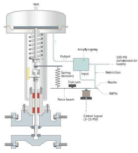
Figure: Typical I/P positioner
It is also possible to use digital signals to control the valve. In this case the I/P positioner receives the signal directly from the fieldbus network in a digital form.
Electric valves
Valves can also be electrically driven. They have the advantage of very accurate positioning. However, air generally provides much faster control and is cheaper.
For an article on the advantages and disadvantages of pneumatic vs electric actuators, read. Note, this is for illustrative purposes only and is not a recommendation or endorsement of the supplier’s product:
Variable speed drives
A variable speed drive, VSD (also known as a variable frequency drive, VFD), allows us to control the frequency and voltage of the electrical current to an electric motor. As the frequency is directly related to the speed of a motor, the motor’s speed can be adjusted. The figure below compares the differences between a VSD and a throttling flow control valve on a system:
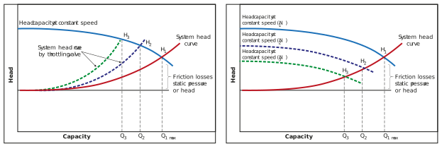
Figure: Controlling flow with a flow control valve and a VSD
As you can see from the first graph, throttling increases head and thus increases pressure losses throughout the system. In the second graph, the reduction in VSD output causes the system to operate at a lower head pressure. This results in power savings.
The following video shows how a VSD works. Note, this is for illustrative purposes only and is not a recommendation or endorsement of the supplier’s product:
To summarise: The AC (alternating current) supply voltage is converted to DC (direct current) using a rectifier. This part of the VSD is often referred to as a DC link. The DC voltage is then converted back to AC. This process is normally done with a technique called pulse width modulation, or PWM. The output voltage is turned on and off. The duration of the on-time, or pulse width, is controlled to present a sinusoidal wave form of the desired frequency. The figure below shows the components and output of a VSD:
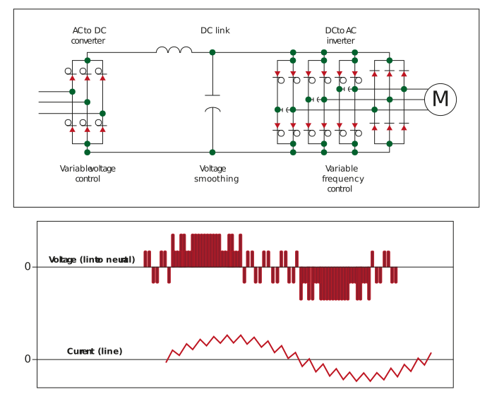
Figure: Components and output of a VSD
There are other ways to change a motor’s output, such as by using adjustable pulleys or hydraulic couplings. VSDs have become more accessible and affordable, so these other methods are no longer commonly used.
Why use VSDs
VSDs are typically more expensive than a control valve; so why do we use them?
Imagine driving a car and having one foot flat on the accelerator and one foot on the brake. This is the equivalent of running a pump full speed with a flow control valve on the line. A VSD is the equivalent of just lifting your foot off the accelerator.
VSDs save energy by reducing the energy reaching the motors. They also save energy as they are typically 97% efficient, whilst motors normally have lower efficiencies. Furthermore, when motors are started, their starting load can contribute to peak demand. This can be managed with a soft starter, but VSDs have a built-in ‘ramp up’, and so eliminate the need for a soft starter on larger motors. Motors are also stressed less by this, which decreases the resultant wear and tear.
VSDs have numerous controls that can be used. They can be used to control torque and slip, amongst other things. They can also be used to reverse direction.
One important thing to remember with VSDs is that most motors have a built-in fan that is driven by the motor shaft. If you reduce the speed of the motor, you also reduce the speed of the fan and the motor can overheat at low speeds. Thus, you can either set a limit on the lower speed, or attach forced cooling to the motor if you need to take the speed to very low values.