
Lesson 2 - Principles of Process Control
This lesson explores exactly what process control is and explains why it is important. It examines the various levels within process control systems and identifies the associated equipment. It also takes a detailed look at the various automation communication and control elements.
Process Communication
Information can be conveyed throughout the process in various ways.
Signals can be used to send the measurements made by an instrument back to the control system. Historically, the most common form of signal used was pneumatic (in the range 20-100 kPa), but this method has become virtually obsolete with electronical advancement.
Automation language can be confusing, and none more so than the terms ‘digital’ and ‘analogue’. A digital input or output is one that only has two possible states – Yes or No. In mathematical terms, this is referred to as a Boolean. An analogue input or output covers a range and is thus a real number.
Conventional digital signals
Each device has its own wire, either relaying signals to the device or from the device. These are then all wired to a panel, where they connect to a digital input or digital output card, and this is then wired to the PLC.
Conventional analogue signals
A standard electrical current of 4-20 mA is most commonly used. Instruments are ranged according to this. So, if the instrument has an output of 0-100 kPa, then 0 kPa will have a signal of 4 mA, and 100 kPa will have a signal of 20 mA. We can also use other signal systems, such as 1-5 V. You may wonder why the ranges do not start at zero? The logic behind this is that any failures will be picked up as a zero signal, allowing for improved fault detection. Analogue inputs and outputs are also fed into the PLC via cards.
Open digital protocols
One big drawback of the conventional system was that only one signal could be communicated. As you can imagine, having separate wires for each instrument can be quite labour intensive and could also make your brewery’s network look like tangled spaghetti. Furthermore, instruments are becoming more and more advanced and have the capability to provide not only information on what they are measuring, but on other parameters too. These devices have outputs for, and can report, faults, failure conditions, service requirements and other parameters. The capabilities of some devices are even greater than this. Without ways to communicate this, this would all be wasted. The first protocol developed to address this need was HART:
HART
The Highway Addressable Remote Transducer (HART) is a system that uses frequency shift keying to transfer digital data along the 4-20 mA system. The figure below shows the principles of how this is done:
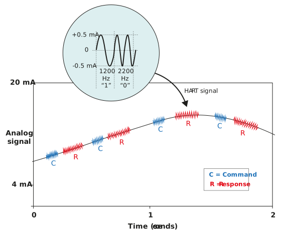
Figure: Digital signals over an analogue connection
The original analogue signal is carried by the average value of signal. The amplitude of the oscillations around this conveys discrete values.
However, this system still requires one set of wires per instrument. The figure below shows a typical HART installation:
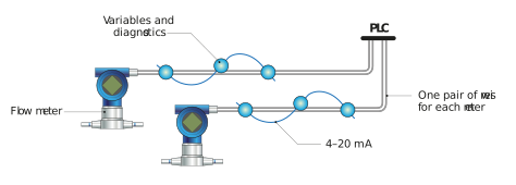
Figure: Typical HART protocol
HART has migrated and improved to allow multiple instruments to be connected to one network. The basis of the HART protocol is still a 4-20 mA signal, but the information is sent across in a digital format.
One benefit of HART is that it can fit onto existing wiring, which helps to keep costs down. However, the 4-20 mA circuit is susceptible to noise and potential false signals can arise as a result of this. The signal speed is also slow compared to the other protocols. HART can thus be used anywhere to upgrade instruments to provide more data whilst still using the existing 4-20 mA wiring, for example to replace a flowmeter with one that can give flowrate and error messages.
The latest offering from HART is HART wireless, which allows for wireless communication.
Fieldbus protocols
A fieldbus is a digital communication link between intelligent devices. Multiple devices can thus be connected within a single network. Data can be sent in both directions.
The two most common protocols are Profibus PA and Foundation Fieldbus. There are some differences between the exact workings of these two protocols.
The figure below shows a typical conventional IO system compared to a fieldbus system:
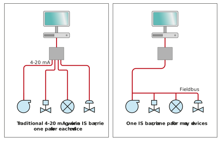
Figure: Comparing conventional wiring to a fieldbus
As you can see, the conventional system requires far more wiring.