
Lesson 13 - Control of Fluid Flow 3 SAQ
This lesson allows you to test yourself on the material covered in the Control of Fluid Flow 3 lesson and determine the level to which you have met the learning outcomes.
Suggested Response - Q4
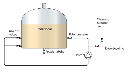
**/***The figure below shows a schematic for a whirlpool in a small craft brewery. Only one pump is used to fill and rotate the whirlpool and also pump-out the whirlpool to wort cooling. This minimises the number of pumps required – the pipework and valving is as shown below. Blue rotational valves are used to ‘spin’ the wort in the whirlpool and to achieve its dual-purpose function. Following the required rest period where the trub would begin to sediment, the black draw-off valves are used to feed wort to the suction of the pump and the red wort cooling valve is opened to allow clarified wort to be pumped to wort cooling.
Cleaning-in-place of the wort main and wort cooler (not shown) is done in the reverse direction and the cleaning solution is returned via the green valve shown. It is required to be able to clean the wort main whilst the whirlpool is in-service and clarifying wort.
Review the schematic and comment on any concern/s you may have on the simultaneous cleaning of the wort main and wort clarification in the whirlpool. What change/s would you make to the plant to address your concern/s whilst still ensuring simultaneous operation?
Response:
This question is not as involved as it first seems. It hinges on the need to simultaneously clean the wort main whilst clarifying wort in the whirlpool. We should avoid, at all costs, contamination of the wort with cleaning solutions, and we are relying on the wort cooling valve (illustrated as red in the image above) not leaking. If it did leak, then cleaning solutions could enter the wort circuit. In short, the integrity of the whirlpool and any wort in it is reliant on this wort cooling valve not leaking.
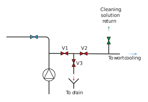
So how could we ensure that the wort cooling valve does not leak? Well, we cannot, but we can ensure that if it does leak, that the leak is properly managed and does not contaminate the wort. We would do this by using a double block and bleed valve assembly. The assembly could take the form of that shown in the figure below (focussed on the wort main valve section).
-
Valves V1 and V2 would be closed during whirlpool operation, and wort main CIP (the exceptional case is described below) and V3 would be open to run the leakage space to an atmospheric drain.
-
During wort cooling, V1 and V2 would be open, and V3 would be closed.
-
During wort main CIP, V2 and V3 would be pulsed open for short durations to clean the leakage space to drain. Yes, it does create a situation where only one valve (V1) closes off the wort main from the whirlpool, which presents a small increased risk but the leakage space is open to atmosphere so the CIP solution should run to drain rather than try to flow through a potential leak in V1 against a positive pressure in the whirlpool circuit.
You can see that the block and bleed assembly is a little involved and replaces the single original wort valve with three valves, so it would be more costly. However, it would give the whirlpool increased leakage protection.