
Lesson 9 - Control of Fluid Flow 1 SAQ
This lesson allows you to test yourself on the material covered in the Control of Fluid Flow 1 lesson and determine the level to which you have met the learning outcomes.
Self-Assessment Questions
-
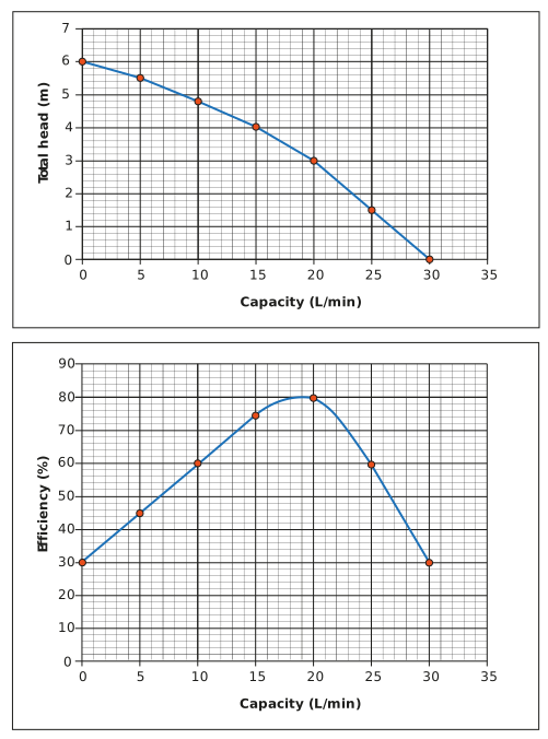
**Two identical centrifugal pumps (pump curve is shown below) are used in series to enhance pumping performance. Sketch the compound pump curve (total head and efficiency) for both pumps.
-
**The two pumps described in question one above are used to pump water against a constant head of 4 m, which may be considered independent of flow rate. If the suction head on the pump is zero, what capacities (flow rates) would a single pump and both pumps be able to generate? And what would the electrical power be for both situations? (The density of water is 1,000 kg/m3).
-
*/**If a pump can deliver a total head of 10 m of water and with reference to the three scenarios shown below, determine the maximum heights of water above the pump outlet that the pump can deliver in the second tank (pipeline pressure losses can be ignored). You should assume that the water level in Tank 1 is maintained at the height specified for each scenario with water from another source during these transfers.
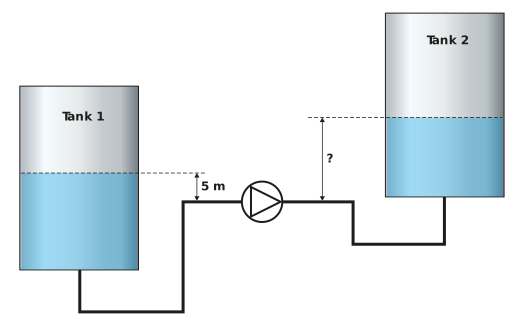
Scenario one – water level in tank 1 is 5 m above the pump inlet
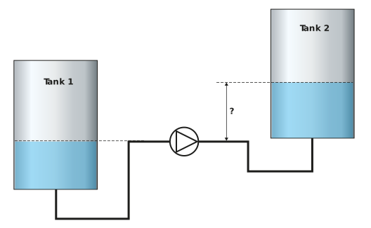
Scenario two – water level in tank 1 is at the level of the pump inlet
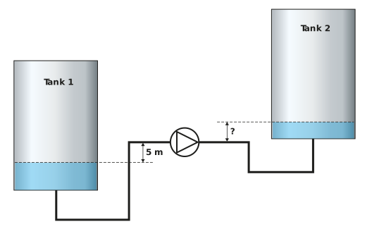
Scenario three – water level in tank 1 is 5 m below the level of the pump inlet (Note: assume pump is self-priming, or that inlet line remains flooded)
-
*/**Describe the principle of operation of a centrifugal pump with reference to Bernoulli’s equation and pump geometry.
-
*Describe the principle of operation of a positive displacement pump.
-
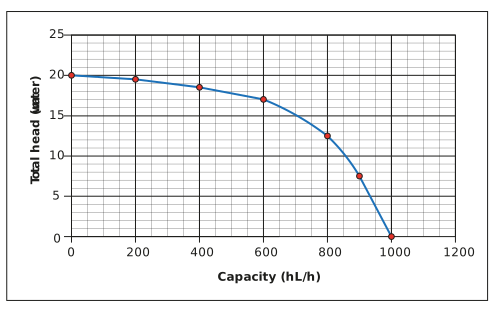
*/**A centrifugal pump is used to bottom fill a tank with water (pump curve below). The base of the tank is 1.5 m above the pump outlet, and the tank has a working (full) level 10 m above its base. What would be the flow rate at the start, mid-point and end of tank filling? A zero-suction head on the pump may be assumed throughout filling, and any pressure loss in the discharge line from the pump to the tank may be ignored.
-
**/***
a) A bright beer main of 100 mm internal diameter is 80 m long. If the friction factor can be considered a constant at 0.005. (This is not a function of line velocity. This is a simplification to assist you in the calculation. We know from our previous studies that friction factor is a function of line velocity). Sketch the characteristic curve for the pipeline between 0 and 1,000 hL/h. Represent the pressure drop as a head in metres of water (ρ = 1,000 kg/m3).
b) If the pump from question six above was used to supply the bright beer main, and a zero-suction head condition existed, what would be the supply flow rate?
Bright beer properties are ρ = 1,010 kg/m3 and µ = 3 cP.