
Lesson 6 - Wort Separation Process Control
This lesson deals with wort separation process control. The different methodologies of measuring and calculating extract recovery are explained and demonstrated. A methodology is explored, as is how to investigate and resolve performance issues with extract efficiency, wort quality, and cycle time.
Point of reflection – reconvene
Welcome back. So, what were your thoughts?
We need to refer back to Darcy’s Law. For any given mash charge and wort separation device, pressure limit/DP, bed depth L and filter cross-sectional area A are fixed. Any change from normal flow rate is likely to be either the grain bed permeability K, or the wort viscosity µ.
We will now follow a flow chart of the process, and identify where these two variables are affected:
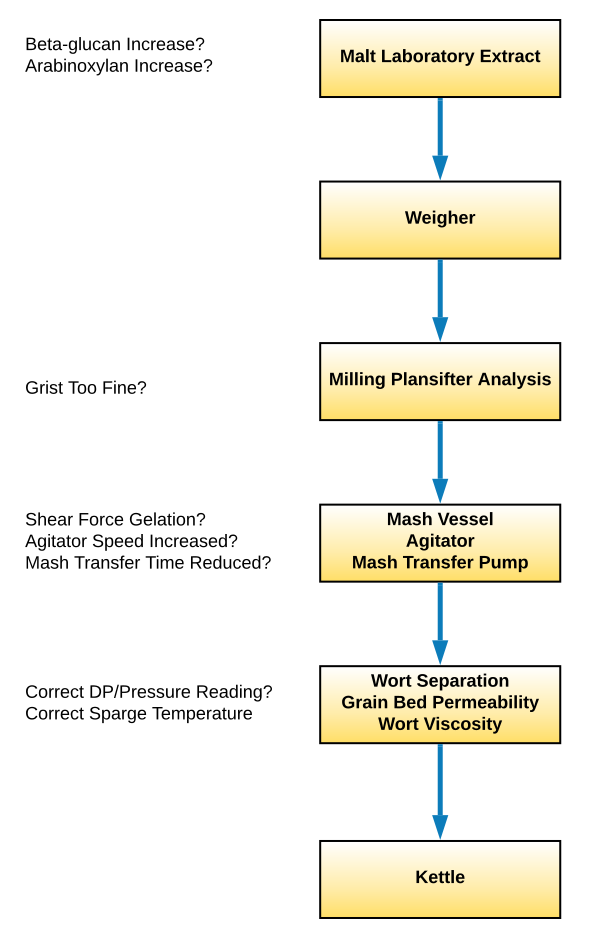
Figure: Troubleshooting slow wort separation
Grain Bed Permeability
The grain bed permeability is largely dependent on the coarseness of the grind. The finer the grind, the lower the bed permeability and the lower the flow.
So, we need to do a plansifter analysis of the grist. If the husk fraction is lower than normal, the grain bed permeability will be lower, and the wort flow rate will reduce. If we do not allow the wort flow to reduce, then instead the DP will increase until the pressure limits of the device are reached. The lauter tun will initiate a deep bed rake. The mash filter will move to pressure control and reduce flow rate. Either will increase cycle time.
It may be, for instance, that to get better extract efficiency we have deliberately created a finer grist at milling, but this is the consequence. There is often a trade-off between extract efficiency and cycle time.
If the friability of the malt has changed, there could be a different husk fraction without us changing anything at all at milling.
Wort Viscosity
Our next investigation is to establish whether wort viscosity has increased. This will either slow down our flow rate or create higher DP. As seen earlier, viscosity will increase with wort gravity. We will know if this has changed when considering our gravity to determine extract efficiency. Our prime suspect here is that the ‘gummy’ material level in our malt is higher than it was. The main indicator of this is in our malt analysis, with β-glucan levels are the main indicator. If this level has increased, then viscosity will have increased. Typical satisfactory values on malt analysis would be β-glucan < 100 mg/L and viscosity < 1.5 cP. However, this depends on the mashing regime and whether a temperature stable fungal β-glucanase is in use. It is also possible that arabinoxylan levels are higher, but these are much more difficult to measure.
Ideally, we should be equipped with a method to measure wort viscosity at the gravity and temperature we are using. This is preferential to inferring from a malt analysis, which uses wort at a relatively low gravity of SG 1.040 or 10 ˚Plato and at 20˚C.
We should also check that the sparge temperature is correct (probe calibration) and that the sparge temperature setpoint has not been reduced. As we saw earlier, viscosity increases with reducing temperature. This is particularly important for the mash tun and lauter tun, which rely on reducing viscosity to ramp up to higher flow rates.
Gelation of Glucans and Proteins
A final factor that will hinder wort separation is the presence of glucans and proteins which have been gelated by high shear forces. These can potentially occur in the mash conversion vessel and the mash transfer pump and pipework.
The mash conversion vessel has an agitator which rotates slowly to keep the mash in suspension. It rotates at higher speeds during mashing-in to help with wetting of the grist. It is also used at higher speeds during heating to ensure good heat transfer at the vessel wall, and avoid mash burning-on. The agitator tip speed should not exceed 2.5 m/s at any time.
The agitator will generally have a variable speed drive. If we have increased agitator speed to improve wetting of the mash or increase the mash heat up rate, then this may lead to poorer wort separation performance.
Similar comments can be made regarding the mash transfer pump and pipework. The pipework will have been designed to avoid severe directional changes and flow restrictions. Large pipework diameters are used to ensure that velocity does not exceed 1.5 m/s. The mash pump should have an open impeller, and its speed should be < 1,000 rpm. If we try to speed up the mash transfer, the rpm of the pump impeller will be higher, and the line velocity will be higher. Both of these may cause gelation due to higher shear forces. So it’s just worth a check that neither of these have been accelerated!
Impact on Brewhouse Capacity of Slow Wort Separation
Let us imagine a lauter tun operating at 10 brews per day (cycle time = 24 h/10 = 2.4 h = 144 min). Slow wort separation normally means an increased number of deep bed rakes. If there is one extra deep bed rake taking 10 min, then the cycle time will increase from 144 min to 154 min, or from 2.4 h to 2.6 h. Our brews/day are now 24 h / 2.6 h = 9.2 So one extra deep bed rake reduces our brewhouse capacity by 8%.
If we have a mash filter operating at 13 brews per day, then its cycle time is 24 h/13 = 1.85 h = 110 min cycle. If slow filtration extends the cycle time by 10 min to 120 min, then the cycle time becomes 120 min or 2 h. Our brews per day are now 24 h/2 = 12 brews per day. This represents an 8% reduction in brewhouse capacity.
Just a 10 min increase in wort separation time can have a significant effect on brewhouse capacity when it is the rate limiting step of the brewhouse.