
Lesson 4 - Milling Principles
This lesson explains the objectives of milling and how mills are designed to achieve them. It details how malt is conditioned for dry milling and how we analyse grist particle size profiles. Finally, it explains how milling affects downstream brewing processes.
Roller Mill Design
A roller mill comes in a variety of types and sizes and is the most widely used design of mill. In a roller mill, grain is passed between two or more pairs of rollers. As the grains pass through the rollers they are comminuted by compression and shear
The figure below shows compressive and shear forces on a cylinder.
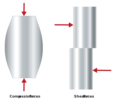
Figure: Compression and shear
Compression causes the grain to deform until it fractures. Shear tears the grain apart. We will now discuss how a roller mill is designed to use compression and shear to achieve our milling objectives.
Feed into the mill
In large breweries a conveyor, usually after the weigher, brings the cleaned and screened malt to a hopper situated above the mill. At smaller breweries, an operator tips malt from sacks into the hopper. At the base of the hopper, a manual or automatic valve is opened to a pre-set percentage to allow the right quantity of grain to flow into the mill. Good mills also have a feed or distribution roller that helps distribute and orientate the grain correctly for milling. The feed roller can be grooved or fluted to allow it to catch the malt grains and drop them into the mill as it rotates. Some modern mills incorporate a rotating malt distribution paddle that separates the grains along its length before dropping them onto the feed roller.
For roller mills to operate effectively, the grains must flow continuously along the full length of the rollers. Ideally, all grains should enter the rollers tip first so that they can be split longitudinally.
Roller design
Mill rollers are designed to work with a specific size of feed material. We can see now why the specification of grain size on the malt specification and the screening of the grains during malt handling are so important. If we introduce different sized grains, we are asking the mill to do something it is not designed to do. Most modern mill rollers have a diameter of around 250 mm, which is ideal to work with our typical grain size. The diameter of the roller affects the size of the nip zone, which in turn affects the rate at which grain can be grabbed (nipped) and drawn between the rollers.
A low roller diameter means a smaller nip zone and a lower rate of throughput.
The figure below shows the nip zone on a pair of rollers.
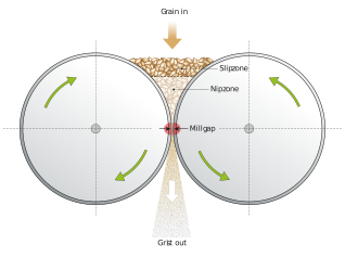
Figure: Nip and slip zones
The size of nip zone is also affected by the mill gap; larger mill gaps reduce the height of the top of the nip zone.
Smaller diameter rollers also provide a smaller area to crush the grain, so they crush it less completely than correctly sized rollers. Think of the difference between rolling a grain between two kegs or two beer cans. The kegs would provide a greater area of crushing, which will increase the time over which each grain is crushed.
The throughput of a pair of rollers is determined by their speed of rotation, the size of the mill gap, and the length of the rollers.
So the longer they are, the faster they turn, and the larger the gap, the more malt the rollers can mill per hr. On a mill with more than one set of rollers, the throughput is determined by the rollers with the slowest rotation, shortest length, and smallest gap.
Roller length varies between mills; low throughput mills designed for small breweries can be smaller than 400 mm whereas mills for large breweries can be up to 1.5 m long.
Fluting
We mentioned at the start of the section that rollers shear as well as crush. One of the reasons for this is the fluting.
Fluting is designed to increase the coefficient of friction (gripping) and shear on the grain as it passes through.
By fluting, we mean grooves that are milled out during manufacture (we are talking about a different sort of milling here, where metal is cut using rotating cutters). There are 6.5-10 flutes per cm of circumference on a typical fluted roller, and this is shown in the figure below.
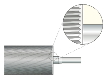
Figure: Roll fluting
As you can see in the diagram, the flutes have a slight twist from the lateral. This is shown in more detail below.
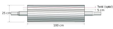
Figure: Twisting of flutes
The reason for this is to increase the shearing action of the flutes. This action is almost like when you wring out washing. Flutes are milled to have a cutting edge which has quite a sharp angle and a rear edge with a shallower angle. In mills with more than one set of rollers, the rollers can be arranged to have cutting edges vs. rear edges, cutting edges vs. cutting edges, or rear edges vs. rear edges. For rollers dealing with husk, there are typically rear edges against rear edges, while for grits you will find cutting edges against cutting edges. When roller milling for a mash filter, all roller sets have cutting edges against cutting edges.