
Lesson 10 - Utilities Part 1 End of Unit SAQ
This lesson allows you to test yourself on the material covered in the Utilities Part 1 unit and determine the level to which you have met the learning outcomes.
Suggested Response - Q2
*** You have a primary refrigeration process using ammonia (R717). The vaporisation temperature is -10°C, and the condensation temperature is 30°C. Saturated vapour leaves the evaporator. The cooling requirement for the brewery is 500 kW.
a) Draw the key points on the Mollier diagram provided.
b) For each stage of the OVC, describe the process the ammonia is undergoing, and the equipment involved.
c) Calculate the COP for the system described.
d) What would the COP be if the ammonia was superheated by 10°C leaving the evaporator, and subcooled by 5°C leaving the condenser?
e) Describe the ways in which the COP can be improved.
f) If the condensation temperature changes to 20°C and the vaporisation temperature changes to -5°C, what will the new COP be?
g) Comment on the COP values you have calculated.
h) Calculate the flow rate of refrigerant required for the initial conditions.
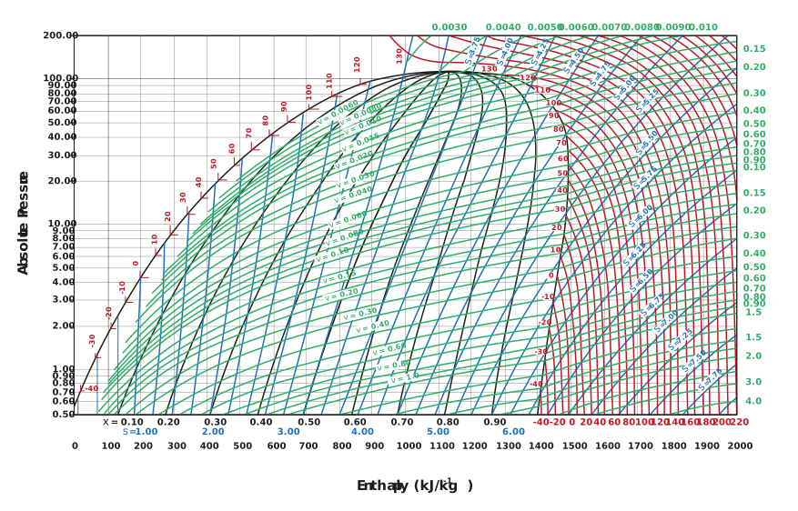
Figure: Mollier diagram for ammonia
Response:
a) The process is shown by the points ABCD.
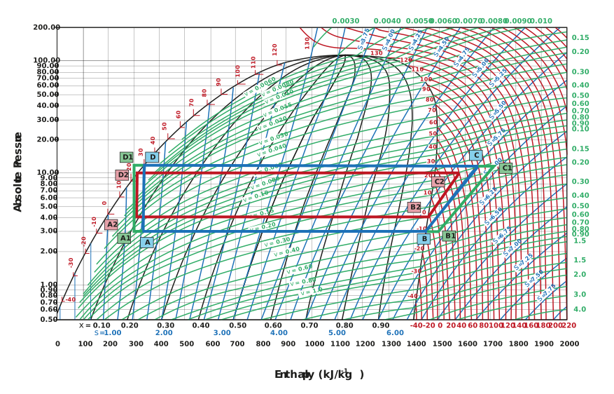
b) AB is the vaporiser. This process happens at constant temperature (isothermic) and constant pressure (isobaric).
BC is the compressor. Here, we have an increase in pressure and temperature. We assume this to be isentropic (constant entropy).
CD is the condenser. This happens at constant pressure (isobaric). The temperature decreases until all the superheat is removed. Thereafter, it occurs at constant temperature (isothermic).
DE is the expansion valve. The pressure and the temperature both drop. This happens at constant enthalpy (isenthalpic).
c) To calculate the cooling load (Qe):

To calculate the compressor work (Qw):

To then calculate the COP:

d) The new cycle is shown by the points A1B1C1D1.
The cooling load (Qe) would be:

The compressor work (Qw) would be:

The COP would then be:

e) COP can be improved by increasing the temperature of evaporation and decreasing the temperature of condensation.
f) The new cycle is shown by the points A2B2C2D2.
The cooling load (Qe) would be:

The compressor work (Qw) would be:

The COP would then be:

g) The second option is more effective as it reduces the work done by the compressor. The first option only provides more cooling, but the compressor duty remains virtually unchanged.
h) If the user requires 500 kW of cooling, which is in fact 500 kJ s-1.
The cooling available is:

Thus, to calculate the flow rate of refrigerant:


