
Lesson 10 - Utilities Part 1 End of Unit SAQ
This lesson allows you to test yourself on the material covered in the Utilities Part 1 unit and determine the level to which you have met the learning outcomes.
Self-Assessment Questions
1. *** A boiler is operating at 900 kPa. It produces saturated steam. The steam lines are long, so the steam loses 5% of its energy by the time it reaches the pressure reducing station. The pressure reducing station reduces the pressure to 200 kPa. From the pressure reducing station, the steam then supplies a heat exchanger at 200 kPa. The condensate leaving the heat exchanger is taken to an atmospheric condensate system.
a) Using a Mollier diagram, indicate the following points on the diagram:
i. A – The steam leaving the boiler
ii. B – The steam entering the pressure reducing station (before the removal of condensate)
iii. C – The steam entering the pressure reducing valve
iv. D – The steam just after the pressure reducing valve
v. E – The condensate leaving the heat exchanger
vi. F – The condensate at the atmospheric condensate tank just before it flashes
vii. G – The condensate after flashing has occurred
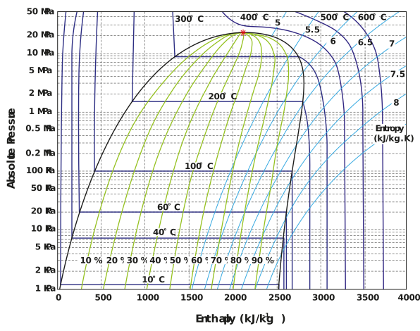
Figure: Mollier diagram for water
b) What is the state of the steam at each of the points in a)?
c) Calculate how much condensate (as a percentage of total steam) will be drained before the pressure reducing station. Assume that you have 100% separation of vapour and liquid. Also assume that there are no pressure losses in the steam line (although we know that is not possible).
d) To what temperature will the steam be superheated after the pressure is reduced if the specific heat of vapour (sg) is 7.7014 kJ kg-1 K-1?
e) How much energy is available to perform heating in the heat exchanger?
f) Calculate the amount of condensate that will flash off in the condensate tank.
g) If the heat exchanger requires 1,000 kg of steam per hour, and the boiler feed water temperature is 20°C, what is the required gas flow rate for the boiler if it has an 80% boiler efficiency and the calorific value of the gas is 44 MJ/kg? Remember to take into account the condensate drained from the before the pressure reducing station calculated in (c) above. For the purposes of this calculation, assume there is no flash steam from this condensate draining point. Also take into account the condensate flash losses calculated in (f) above.
Assume condensate is returned to the boiler at 100°C.
Steam table information for SAQ 1 is as follows:
Table: Saturation temperature table for steam in SI units
|
T |
Psat |
hf |
hg |
hfg |
|
°C |
kPa |
kJkg-1 |
kJkg-1 |
kJkg-1 |
|
0 |
0.6119 |
0.9007 |
2,500.02 |
2,499.12 |
|
10 |
1.2282 |
42.2477 |
2,520.42 |
2,477.27 |
|
20 |
2.3376 |
84.2043 |
2,538.85 |
2,454.65 |
|
30 |
4.242 |
125.811 |
2,556.81 |
2,431 |
|
40 |
7.3743 |
167.452 |
2,574.65 |
2,407.2 |
|
50 |
12.333 |
209.15 |
2,592.34 |
2,383.19 |
|
60 |
19.916 |
250.918 |
2,609.8 |
2,358.89 |
|
70 |
31.156 |
292.765 |
2,626.94 |
2,334.18 |
|
80 |
47.353 |
334.696 |
2,643.69 |
2,303.9 |
|
90 |
70.104 |
376.72 |
2,660.01 |
2,283.29 |
|
100 |
101.325 |
418.849 |
2,675.84 |
2,256.99 |
|
110 |
143.273 |
461.099 |
2,691.14 |
2,230.04 |
Table: Saturation pressure table for steam in SI units
|
P |
Tsat |
hf |
hg |
hfg |
|
kPa |
°C |
kJkg-1 |
kJkg-1 |
kJkg-1 |
|
100 |
99.63 |
417.31 |
2,675.27 |
2,257.96 |
|
200 |
120.23 |
504.47 |
2,706.17 |
2,291.7 |
|
300 |
133.54 |
561.16 |
2,724.63 |
2,163.47 |
|
400 |
143.62 |
604.37 |
2,737.68 |
2,133.31 |
|
500 |
151.84 |
639.79 |
2,747.64 |
2,107.86 |
|
600 |
158.83 |
670.07 |
2,755.6 |
2,085.52 |
|
700 |
164.95 |
696.7 |
2,762.13 |
2,065.43 |
|
800 |
170.4 |
720.57 |
2,767.61 |
2,047.05 |
|
900 |
175.35 |
742.27 |
2,772.27 |
2,030 |
|
1000 |
179.87 |
762.23 |
2,776.28 |
2,014.05 |
|
1250 |
189.8 |
806.32 |
2,784.16 |
1,977.84 |
|
1500 |
198.28 |
844.32 |
2,789.84 |
1,945.52 |
Please note:
hf is the specific enthalpy of the water
hfg is the specific enthalpy of evaporation
hg is the specific enthalpy of steam
2. *** You have a primary refrigeration process using ammonia (R717). The vaporisation temperature is -10°C, and the condensation temperature is 30°C. Saturated vapour leaves the evaporator. The cooling requirement for the brewery is 500 kW.
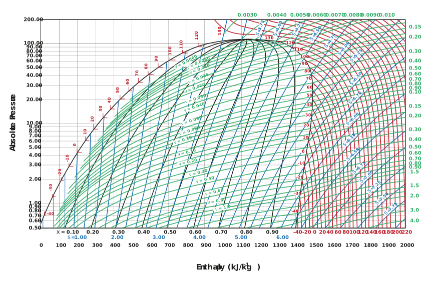
Figure: Mollier diagram for ammonia
a) Draw the key points on the Mollier diagram provided.
b) For each stage of the OVC, describe the process the ammonia is undergoing, and the equipment involved.
c) Calculate the COP for the system described.
d) What would the COP be if the ammonia was superheated by 10°C leaving the evaporator, and subcooled by 5°C leaving the condenser?
e) Describe the ways in which the COP can be improved.
f) If the condensation temperature changes to 20°C and the vaporisation temperature changes to -5°C, what will the new COP be?
g) Comment on the COP values you have calculated.
h) Calculate the flow rate of refrigerant required for the initial conditions.