
Lesson 7 - Refrigeration Theory and Cycle SAQ
This lesson allows you to test yourself on the material covered in the Refrigeration Cycle and Theory lesson and determine the level to which you have met the learning outcomes.
Suggested Response - Q3
** Using the Mollier diagram below, answer the following questions.
Consider a refrigeration process that operates between 15 bar a and 2 bar a. The condenser condenses the refrigerant to a saturated liquid.
a) What is the cooling load?
b) What is the COP of the refrigeration process?
c) How might you enhance the COP of the refrigeration plant?
d) If this refrigeration process was actually a heat pumping process, what would the COP be?
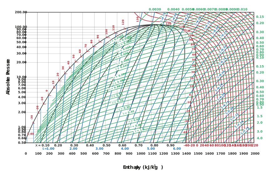
Figure: Mollier diagram for ammonia
Response:
a) The cooling load is the difference in specific enthalpy between the entrance and exit of the evaporator; we will call these values and respectively.

The exit of the evaporator is a saturated vapour at the lower operating pressure of 2 bar a. Consulting the Mollier diagram, we can follow the 2 bar a line to the right, over the phase envelope. Where the line meets the saturated vapour line, is known as the corresponding enthalpy. The exit enthalpy (h2) is around 1,425 kJ kg-1.
The entrance of the evaporator is a mixture of liquid and vapour. It is thus difficult to determine its exact point on a Mollier diagram. However, the enthalpy of the entrance to the evaporator is the same as the exit of the condenser. This is because the expansion valve is assumed to operate with constant enthalpy. The exit of the condenser is a saturated liquid at the higher operating pressure of 15 bar a. The entering enthalpy (h1) is around 375 kJ kg-1.
Finally, we can calculate the cooling load Qe:

b) The COP for a refrigeration system is the ratio of the cooling load (Qe) to the work done by the compressor (Qw).

We determined Qe in part a), so we now need to determine the work done by the compressor. The work carried out by the compressor is the difference between the specific enthalpy of the refrigerant at the entrance and exit of the compressor, h2 and h3 respectively.

We already have the value for h2, so we just need to determine the value for h3. The exit of the compressor is a superheated vapour at the higher operating pressure of 15 bar a. The key thing to remember about the compressor is that we can assume it operates isentropically. So we can start at the exit of the evaporator (entrance of the compressor) and follow the blue isentropic lines up to 15 bar a. Consulting the Mollier diagram, we can determine that h3 is around 1,800 kJ kg-1.
We can then calculate the work carried out by the compressor:

Finally, we can calculate the COP:

Please note, this value is notably low for a COP.
c) The COP can be enhanced in several ways:
-
Increase the evaporation temperature/pressure.
-
Decrease the condensation temperature/pressure.
-
Condense the refrigerant into a sub-cooled liquid instead of a saturated liquid.
d) The COP of a heat pump (COPh) as derived in the preceding lesson is:

