
Lesson 8 - Hygiene End of Unit SAQ
This lesson allows you to test yourself on the material covered in the Hygiene unit, and determine the level to which you have attained the unit’s outcomes.
Suggested Response - Q3
*** Your brewery has 30 fermenters and is using a manual fermenter CIP system with which to clean them. You have been tasked to investigate a new system for your current capacity that will be able to accommodate future expansion.
a. With the help of diagrams, describe which system you would recommend, including its operation and automation.
b. After a week of operation, stock counts are showing a higher caustic use than the manual system! How do you investigate this and ensure that you reduce caustic moving forward?
Response:
a. The question implies that your brewery is medium-sized. Therefore, any single-use system that it might have employed is likely to be inadequate.
A more appropriate system would be a multi-vessel, multi-use CIP system.
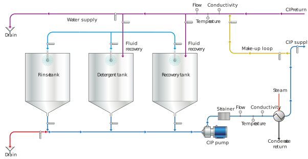
Figure: A multi-vessel CIP system
The figure above shows a single caustic detergent vessel. However, there are options to add a 2nd detergent tank, which is typically an acid tank. This layout shows flexibility for hot CIP via steam heating, although fermenters are re-cleaned at ambient temperatures to prevent the risk of implosion.
The automated CIP system would operate as follows, with a scavenge pump connected underneath to return liquid to the CIP plant:
i. The fermenting vessel is blown down with air, through the bungline, to remove CO2. The air valve is closed.
ii. The detergent tank outlet and return are opened, and detergent is circulated through the CIP station internal loop and dosed with chemical to a predetermined conductivity setpoint. The detergent tank is then closed.
iii. The recovery tank is opened and recovered water is pumped to the fermenting vessel (FV) sprayball; it is then scavenged to drain. This can be continuous but is often in burst rinses. When the recovery tank is empty, the tank closes.
iv. The caustic outlet is opened, and caustic is pumped to the FV. It is scavenged to drain until conductivity starts to rise, whereupon the drain is closed, and the caustic tank inlet is opened to allow caustic recirculation. This may typically last 30 minutes. After the circulation time, the caustic tank outlet is closed.
v. The fresh rinse water tank is opened, and fresh water is pumped to FV to rinse caustic. The scavenge pump returns the caustic/water rinse to top up the caustic tank if it is not already at an acceptable level. When the caustic tank is full, the recovery tank inlet is opened, and the tank is filled.
vi. Step 4 is repeated from the 2nd detergent tank (acid) for 15 minutes.
vii. The fresh rinse water tank is opened, and fresh water is pumped to the FV to rinse the acid. The scavenge pump returns the acid/water rinse to top up the acid tank if it is not already at an acceptable level. The rinse then continues to drain until conductivity drops or the timer runs down.
viii. The sanitiser is dosed into the water stream at a fixed ratio to sanitise the FV. Scavenged sanitiser is returned to drain for 5 minutes.
ix. Sanitiser dosing stops, and sanitiser is removed by sanitised water (typically ClO2 treated), or optionally left in the FV to decompose (if peroxide based).
b. If we are using an automated CIP system, this means that we are relying on instrumentation and not operator completion of the cleaning cycle. We must thus ensure that the automation and control are working correctly.
Detergent makeup dosing will vary and this is the first area to investigate:
i. Are there any leaks on the dosing system?
ii. Is the conductivity meter working; is it calibrated?
Next, is the control on the CIP circulation automation operating correctly?
i. Are the valves sequencing correctly? It could be that caustic is being pushed to drain. Take samples at the drain and check for residual caustic.
ii. Are the level controls in the tanks set correctly to prevent overflow? Are they operating correctly? If a vessel is showing a false high level, this will result in lost caustic.
iii. Are the pumps balanced to ensure that interface liquids do not mix?
Thirdly, are there processing issues?
i. Is there residual CO2 in the tank? This will react with caustic to form sodium carbonate. We must check our vessel evacuation process, as well as the carbonate levels in the caustic after CIP.
ii. Is the caustic excessively foaming out of the CIP vessel? Caustic is prone to foaming due to saponification reactions with lipids contained in the trub ring residue in the fermenter. We must remove as much FV soil as possible with the pre-rinse. This needs to be optimised, possibly through burst rinsing and sacrificial caustic dosing into the pre-rinse.
iii. Confirm the sacrificial caustic concentration. If this is higher than specified, this could lead to caustic loss.
This investigation would form the basis of an optimisation project, which also needs to ensure that the maintenance program for the CIP plant is optimised. Inputs and outputs must be monitored by operators and laboratory personnel.